Data Communication method, terminal equipment, interconnecting installation, data communication system and recording medium

a data communication system and data communication technology, applied in the field of data communication system and data communication method, can solve the problems of packet loss, the throughput of the access link is usually slow, and the throughput of the end-to-end communication is usually slow, so as to enhance communication efficiency and minimize the overhead of packet headers

Inactive Publication Date: 2005-10-11
NEC CORP
View PDF13 Cites 43 Cited by
  • Summary
  • Abstract
  • Description
  • Claims
  • Application Information

AI Technical Summary

Benefits of technology

[0159]The present invention has been developed to solve the above-described problems of the conventional technique, and an object thereof is to provide a data communication method and a data communication system which minimize the overhead of a packet header to enhance the communication efficiency.

Problems solved by technology

In the mobile computing or the remote access, the communication speed of the access link is usually slow, and the throughput of the access link bottlenecks the throughput of the end—end communication in many cases.
Additionally, when an error occurs in a part of the data during the transmission of the packet via the communication media, or when the router is not provided with a sufficient packet storage area, the received packet is discarded, so that packet loss occurs during communication.
When the value of RTT becomes larger than the fixed value, wasteful re-sending occurs.
Moreover, when the fixed value is set to a larger value, much time is required for detecting the loss of the TCP segment.
Moreover, in the data communication system using the TCP / IP, when the conventional TCP segment loss is detected by assuming the TCP segment loss as the discard of the TCP segment by router congestion, the TCP module once lowers the projection speed of the TCP segment to reduce the router processing load, and subsequently increases the speed gradually, which is a technique called slow start.
However, many of the existing communication interface controllers are not provided with interfaces for accepting the push request to the processor.
However, the processing of the received urgent data is not defined (relies on the reception side).
In the above-described conventional data communication method, however, the following problems are caused.
A first problem is that the communication efficiency in the access link is largely deteriorated by the overhead of the TCP header and IP header.
A second problem is that when the packet is lost, the influence of the communication efficiency deteriorated by the packet re-sending is exerted on other section, and the communication efficiency of the other section is deteriorated.
A third problem is that when the re-sending is performed because of the packet loss in the access link section, the throughput is lowered by the TCP congestion control.
However, since the packet loss in the access link has no relation to the congestion in the network, the packet transmission suppression by the slow start has no effect, and the throughput is lowered by suppressing the traffic.
A fourth problem is that the transfer efficiency is deteriorated by delay increase or more with respect to the delay increase of packet transfer in the access link.
This causes the incorrect detection of the packet loss and the subsequent wasteful re-sending processing, the unnecessary packet transmission suppression by the application of slow start, and the like.
In this case, when a packet error occurs by radio line quality deterioration such as phasing, the error control is performed by re-sending with the data link protocol.
Therefore, the packet transfer delay increases when seen from the TCP.
However, the fluctuation property of the delay is different from that of the congestion, and depends on the occurrence timing of a bit error by phasing.
Therefore, delay time depends on the occurrence degree of the bit error and the error control system in the data link protocol.
A fifth problem is that when the packet is lost in the access link, the time dependent on the RTT till then is required for detecting the packet loss.
Therefore, even when the transmission of the TCP segment for the transmission window size is completed until the timeout of the re-sending time, the communication efficiency is deteriorated.
A sixth problem is that when the packet re-sending is performed, even the packet having succeeded in transmission is sometimes resent, and the communication efficiency is deteriorated more than necessary.
Therefore, the transmission-side TCP module cannot know the reception situation on and after the non-received application data.
It is wasteful to re-send the application data which has succeeded in transmission.

Method used


Image

  • Data Communication method, terminal equipment, interconnecting installation, data communication system and recording medium
  • Data Communication method, terminal equipment, interconnecting installation, data communication system and recording medium
  • Data Communication method, terminal equipment, interconnecting installation, data communication system and recording medium

Examples


first embodiment

1. First Embodiment

[0242]A first embodiment of the present invention will next be described in detail with reference to the drawings.

[0243]The function of the data communication system is broadly divided into the following three. Specifically, they are a connection opening function, a connection close function, and a data communication function. Among these three functions, the connection opening function and connection close function as connection control functions will be described in the first embodiment.

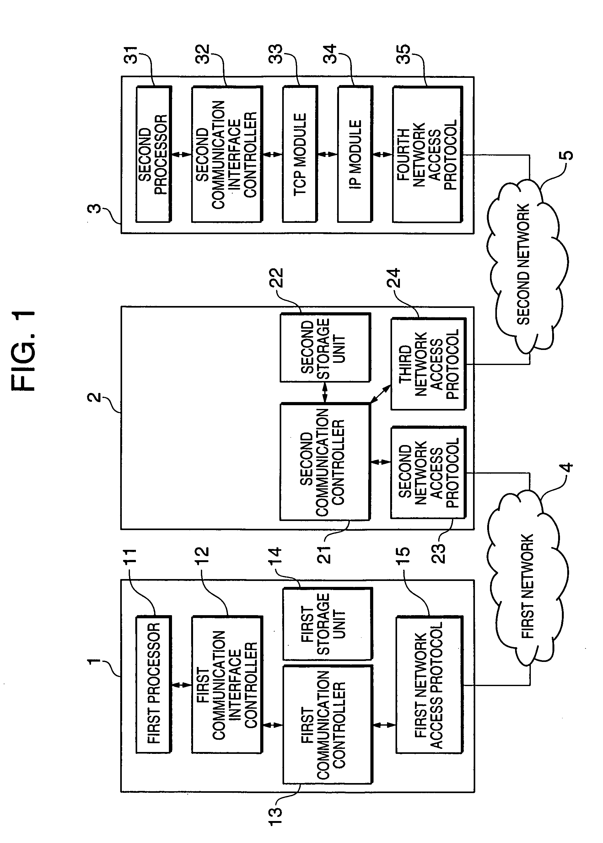
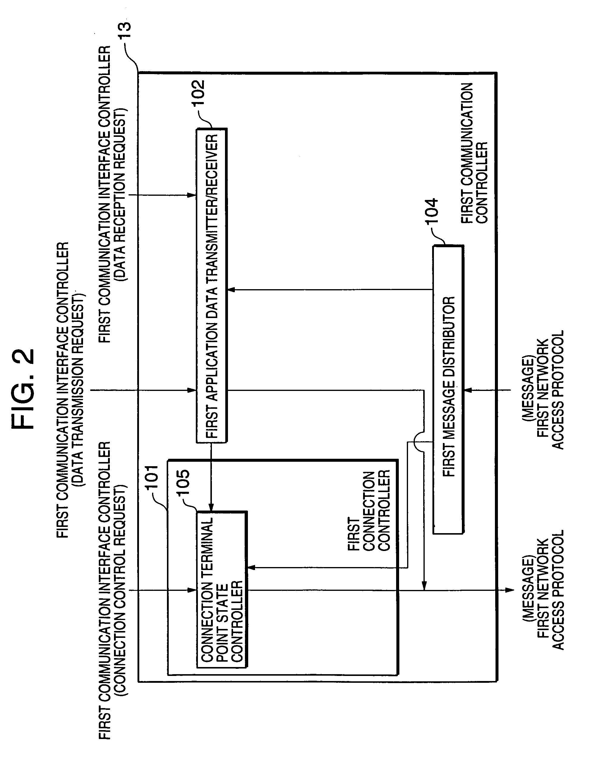
[0244]FIG. 1 is a block diagram showing one constitution example of the data communication system of the present invention. FIG. 2 is a diagram showing the constitution of the first embodiment of the data communication system of the present invention, and is a block diagram showing the constitution of a first communication controller shown in FIG. 1. FIG. 3 is a diagram showing the constitution of the first embodiment of the data communication system of the present invention, and...

second embodiment

2. Second Embodiment

[0397]A second embodiment of the data communication system of the present invention will next be described with reference to the drawings.

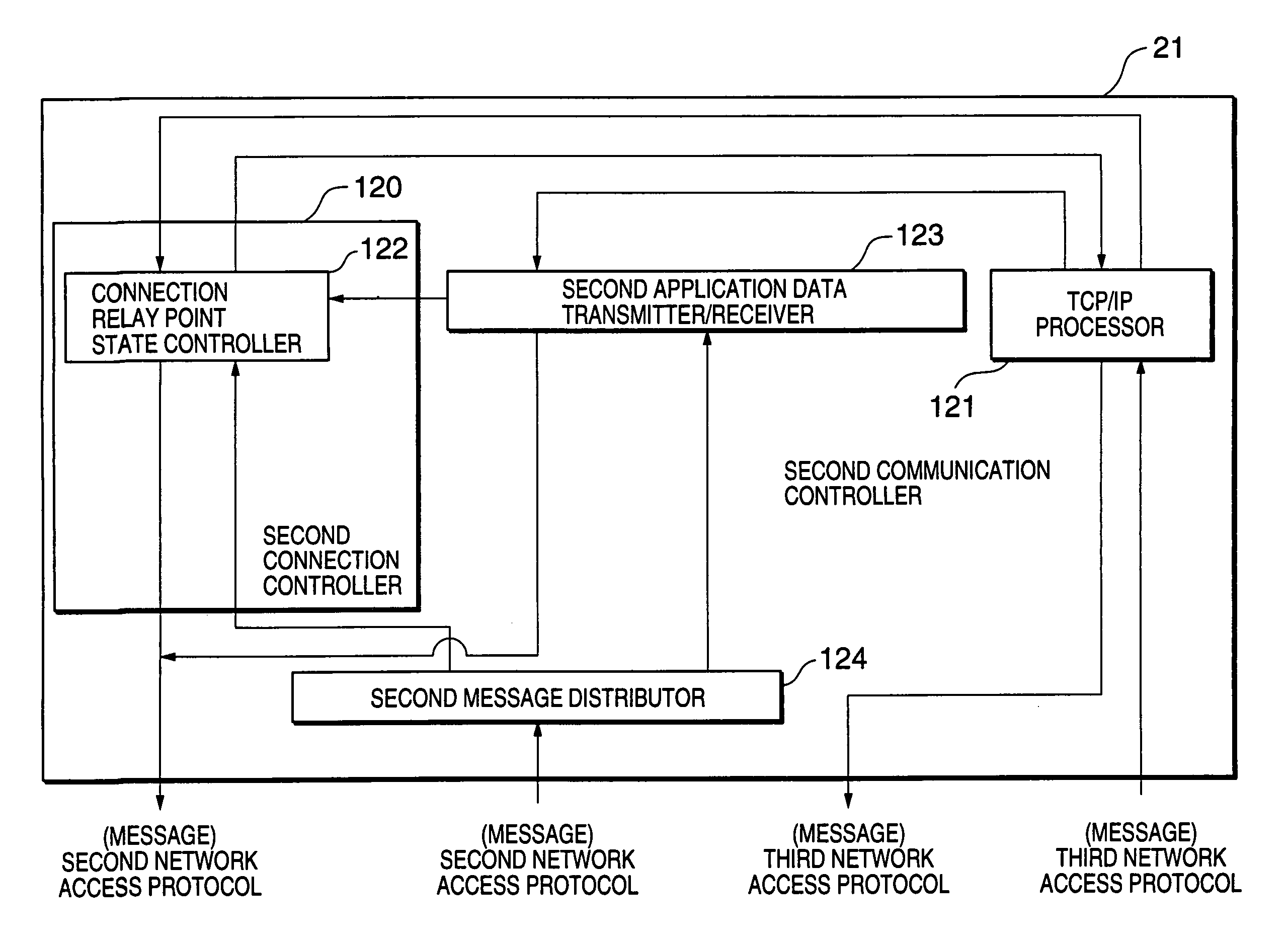
[0398]FIG. 10 is a diagram showing the constitution of the second embodiment of the data communication system of the present invention, and is a block diagram showing the constitution of the first communication controller shown in FIG. 1. FIG. 11 is a diagram showing the constitution of the second embodiment of the data communication system of the present invention, and is a block diagram showing the constitution of the second communication controller shown in FIG. 1.

[0399]The data communication system of the present embodiment is, as shown in FIG. 10, provided with a first connection control message controller 106 in the first connection controller of the first communication controller, and is, as shown in FIG. 11, provided with a second connection control message controller 126 in the second connection controller of the secon...

third embodiment

3. Third Embodiment

[0414]A third embodiment of the data communication system of the present invention will next be described with reference to the drawings.

[0415]In the third embodiment, the data communication function of the data communication system of the present invention (data transmission function, data reception function) will be described. Additionally, for the data communication system of the third embodiment, the constitutions of the first and second communication controllers shown in FIG. 1 are different from those of the first and second embodiments. Since the other constitutions are similar to those of the first embodiment, the description thereof is omitted.

[0416]FIG. 13 is a diagram showing the constitution of the third embodiment of the data communication system of the present invention, and is a block diagram showing the constitution of the first communication controller shown in FIG. 1.

[0417]FIG. 14 is a diagram showing the constitution of the third embodiment of t...


PUM


Abstract

In data communication between a terminal equipment connected to a first network and a second network and a server terminal equipment via an interconnecting installation, there are provided a first communication controller in which data communication control is performed on the terminal equipment via the first network by a message group for functions of data transfer, transmission acknowledgment, flow control, and the like, and a second communication controller in which the data communication control is performed on the interconnecting installation with the terminal equipment via the first network by the message group, and the data communication control is performed with TCP module of the server terminal equipment according to TCP. By this, data communication efficiency is enhanced in a communication environment for communicating a communication terminal equipment on a cable network through a radio line or another access link.

Description

BACKGROUND OF THE INVENTION[0001]1. Field of the Invention[0002]The present invention relates to a data communication method and a data communication system which can realize communication under TCP / IP protocol having a good communication efficiency in application environments such as mobile computing and remote access, in which the throughput for access link from a terminal equipment bottlenecks the throughput in end—end communication.[0003]2. Description of the Prior Art[0004]In recent years, Internet has spread as a network for performing data communication between terminal equipment such as computers. Moreover, an application mode called mobile computing or remote access has spread together.[0005]In the mobile computing and the remote access, as a user's terminal equipment used is an information processor provided with a communication apparatus which can realize communication with radio telephone lines such as a cellular phone and cable telephone lines such as ISDN. Moreover, in...

Claims


Application Information

Patent Timeline
Patent Type & Authority Patents(United States)
IPC IPC(8): H04L29/06
CPCH04L29/06H04L9/40
Inventor TAKEDA, KENJIOSAWA, TOMOKI
Owner NEC CORP
Why Eureka
Try Eureka