Clutch unit

a technology of clutch unit and rotary knob, which is applied in the direction of chairs, movable seats, transportation and packaging, etc., can solve the problems of reducing the frictional resistance of slipping, limiting the design of vehicle body and seat, and requiring a complex structure, so as to improve the frictional resistance to slippage, increase the oil film strength, and improve the effect of oil film formation

Inactive Publication Date: 2005-10-18
NTN CORP
View PDF20 Cites 30 Cited by
  • Summary
  • Abstract
  • Description
  • Claims
  • Application Information

AI Technical Summary

Benefits of technology

[0067]Here, the viscosity of 750 cSt is a value at 25° C. (in this specification, base oil viscosities will all be shown in values for 25° C.). In general, a base oil of lubricating grease for use in this type of clutch has viscosity of 100 cSt or so. When the viscosity of the base oil is equal to or greater than 750 cSt, the lubricating grease enhances in the power for oil film formation so that lubricating oil films of greater oil film strength and oil film thickness are formed around the locking means. This lowers the frictional resistance to a slip when the locking means shifts from a locked state to a lock released state. In addition, the increased oil film strength and oil film thickness enhance the effect of relieving a vibration impact. As a result, the shift operation of the locking means is smoothened, which reduces the operating force and suppresses the occurrence of vibrations and vibrating noise on the shift motion.
[0068]A solid lubricant or an extreme pressure additive may be added to the lubricating grease. Consequently, the frictional resistance can be reduced further to enhance the foregoing effect. The solid lubricant may be PTFE or graphite, and the extreme pressure additive may be molybdenum disulfide or organic molybdenum, for example.
[0069]When rollers are used as the engaging members, their rolling contact surfaces may be given crowning. This suppresses edge load at the contact portions with the rolling contact surfaces of the rollers, promoting the formation of oil films by the lubricating grease. Here, “crowning” refers to providing a slight curvature to the rolling contact surface of a roller. It includes the structure that the rolling contact surface is given curvatures at the areas of both ends, as well as so-called full crowning in which the entire rolling contact surface traces a single curvature. So-called cut crowning in which the crowning areas are drawn in straight lines (oblique lines) is also included. When the rolling contact surface is given crowning at the areas of both ends, the amount of crowning (the axial length and the amount of radial drop of the crowning area) may differ between right and left. Moreover, when the rolling contact surface is given full crowning, the center of curvature of the crowning may be axially offset with respect to the axial center position of the roller. Aside from the foregoing effect, the rolling contact surface of the roller becomes uneven in contact surface pressure. It is therefore possible to generate a skew of the roller (a phenomenon in which the axis of the roller tilts with respect to the axis of the clutch) at the time of shift from the locked state to the lock released state. Consequently, the wedge-engaged part (line-contact part) of the roller gradually comes out from one of the axial ends to the other, with reduced frictional resistance during the shift motion. This smoothens the shift motion of the locking means, thereby reducing the operating force and suppressing the occurrence of vibrations and vibrating noise during the shift motion. Otherwise, the skew generating means may use the structure that the rolling contact surface of the roller and contact surface contact therewith are given surface properties that differ between right and left with respect to the axial center position of the roller. Specifically, it is possible to change the surface roughness of the contact surface partially {for example, apply dimpling (such as shot peening) partially}, or apply friction reducing treatment to the contact surface (for example, apply coating for reducing friction, such as phosphate coating).
[0070]The clutch unit of the present invention is suitable for a seat-adjusting device of a motor vehicle. In that case, the input-side member is connected to an operation lever and the output-side member is connected to a rotating member of the seat-adjusting device. The seat-adjusting device here includes a seat-height-adjusting device for adjusting the height of a sitting seat, a seat-inclination-adjusting device for adjusting the inclination of a back seat, and a seat-slide-adjusting device for adjusting the front-and-back position of a sitting seat. Of these, it is a seat-height-adjusting device of a sitting seat that the clutch unit of the present invention is particularly suitable for. According to this structure, the height of the sitting seat can be adjusted by operating the operation lever to swing. This can enhance operational convenience as compared to conventional device, and increase the design flexibility of the car body and the seat, being extremely useful to a seat-height-adjusting device of a compact car or a popular car in particular.

Problems solved by technology

The seat-height-adjusting device of the prior art requires inconvenient operation of rotating the knob while the driver inserts his hand in a narrow space between the sitting seat and the vehicle body.
Also, the necessity to secure such space imposes limits to the design of the vehicle body and the seat, which can be a burden particularly for small vehicles.
However, this device requires a complex structure, and also has the problem of noise generated by toothed ratchet gears when the lever returns.

Method used


Image

  • Clutch unit
  • Clutch unit
  • Clutch unit

Examples


first embodiment

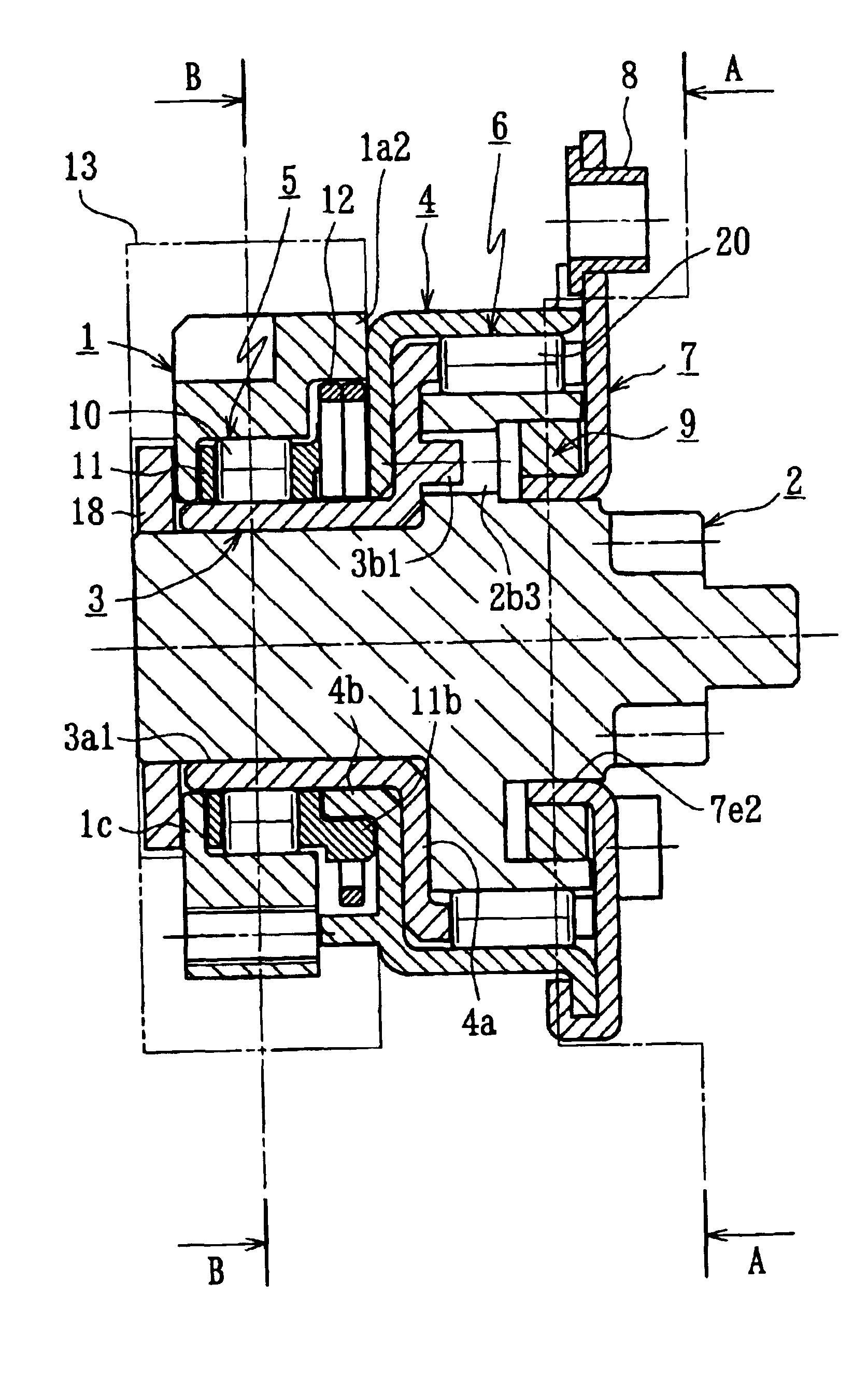
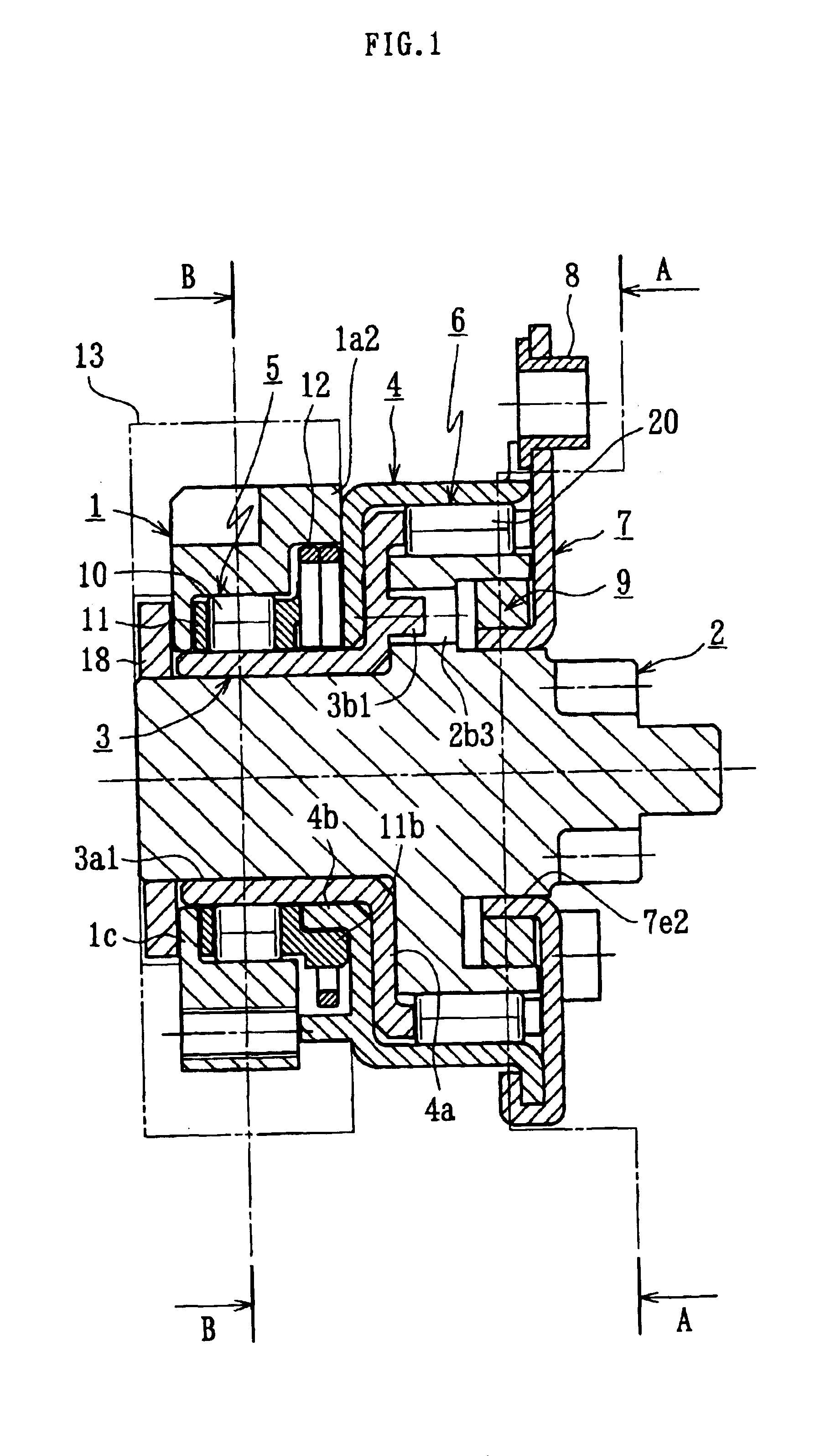
[0142]FIG. 1 shows the overall structure of a clutch unit according to the present invention. The clutch unit comprises an outer ring 1 serving as an input-side member, an output shaft 2 serving as an output-side member, an inner ring 3 serving as a control member, an outer ring 4 serving as a stationary-side member, a first clutch part 5 interposed between the outer ring 1 and the inner ring 3, and a second clutch part 6 interposed between the outer ring 4 and the output shaft 2.

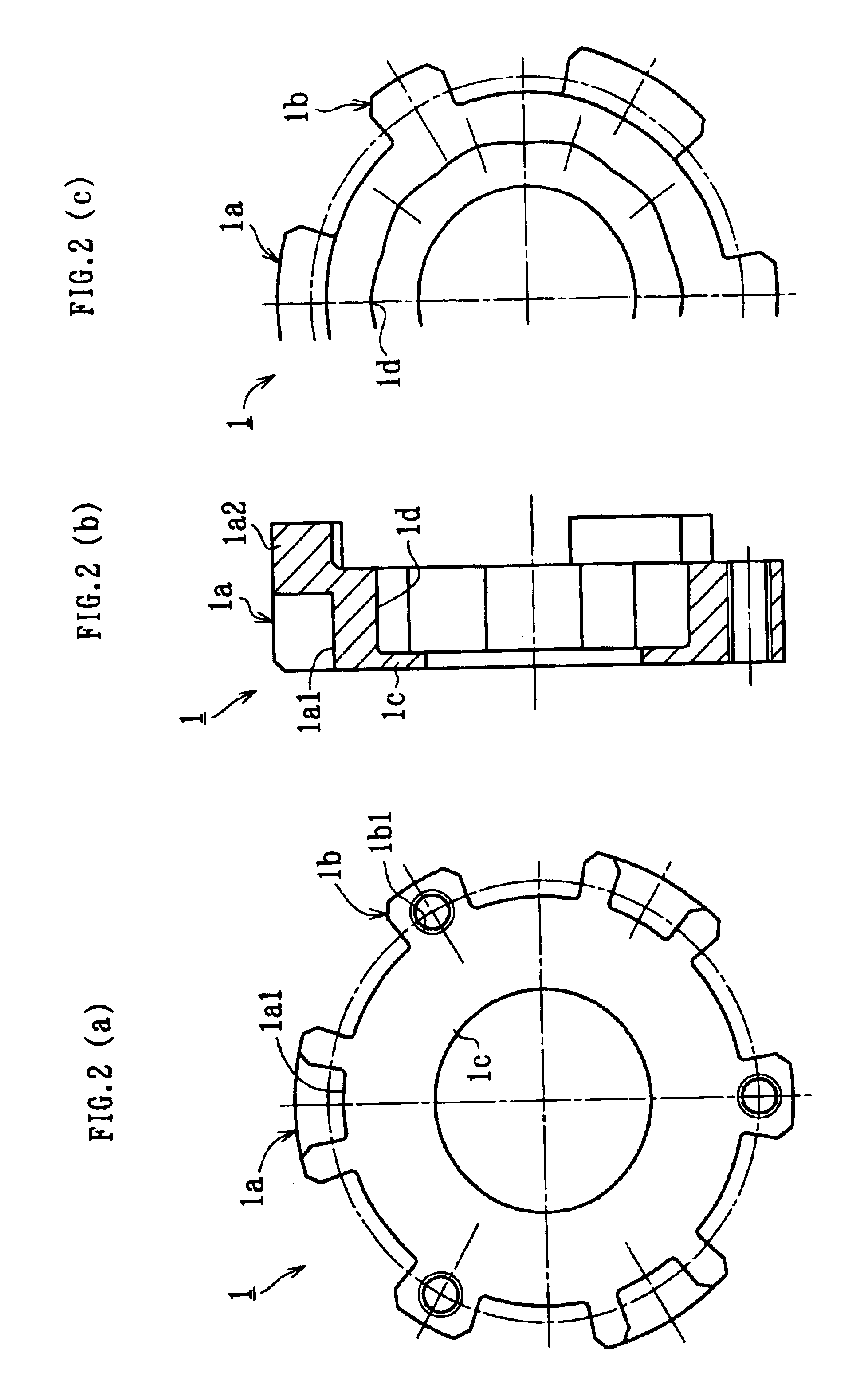
[0143]FIG. 2 shows the outer ring 1, which serves as an input-side member. The outer ring 1 has a plurality of protruding ribs 1a and 1b, for example three each, as in the illustrated example, at spaced intervals around the outer circumference thereof. One end portion of the rib 1a in its axial direction is divided into two by a recess 1a1, while the other end thereof extends from the end of the outer ring 1 along the axis for forming a protrusion 1a2. Each of the ribs 1b has a screw hole 1b1 formed therein...

fourth embodiment

[0183]FIG. 22 shows the entire structure of a clutch unit according to the present invention. The clutch unit of this embodiment comprises an outer ring 1 as an input-side member, an output shaft 2 as an output-side member, an inner ring 3 as a control member, an outer ring 4 as a stationary-side member, a first clutch part 5 arranged between the outer ring 1 and the inner ring 3, and a second clutch part 6 arranged between the outer ring 4 and the output shaft 2.

[0184]FIG. 23 shows the outer ring 1, as the input-side member. A plurality (three, for example) of ribs 1a, a plurality (four, for example) of ribs 1b, a plurality (two, for example) of ribs 1e, and one or more ribs 1f protruding outward are formed on the outer periphery of the outer ring 1 at predetermined circumferential intervals. An axial end portion of each rib 1a axially protrudes from an end of the outer ring 1, thereby forming a protruding portion 1a2. In addition, the outer periphery of any one of the three ribs 1...

fifth embodiment

[0234]FIG. 49 shows a clutch unit which is the input-side part of the clutch unit (FIG. 54) according to the present invention to be described later, exclusively configured as an independent clutch unit.

[0235]This clutch unit comprises an outer ring 1′ as an input-side member, an inner ring 2′ as an output-side member, a plurality of rollers 3′ as engaging members, a retainer 4′ for retaining the rollers 3′, and an elastic member attached to the retainer 4, such as a centering spring 5′.

[0236]The outer ring 1′ is composed of a first thin member 1A′ shown in FIG. 50 and a second thin member 1B′ shown in FIG. 51. These thin members 1A′ and 1B′ are both fabricated by press-forming a steel plate. Incidentally, for example, the second thin member 1B′ may be made of a molded product of resin or the like if necessary.

[0237]The first thin member 1A′ comprises a cylindrical portion 1Ab′ having a plurality of cam surfaces 1Aa′ formed on an inner periphery thereof at regular circumferential in...


PUM


Abstract

A clutch unit comprises an outer ring 1 as an input-side member, an output shaft 2 as an output-side member, an inner ring 3 as a control member, an outer ring 4 as a stationary-side member, a first clutch part 5 interposed between the outer ring 1 and the inner ring 3m, and a second clutch part 6 interposed between the outer ring 4 and the output shaft 2. Input torque input from an operation lever 13 is transmitted in the path of the outer ring 1→the first clutch part 5→the inner ring 3→the output shaft 2. Reverse input torque input from the output shaft 2 is locked with the outer ring 4 through the second clutch part 6.

Description

CROSS-REFERENCE TO RELATED APPLICATION[0001]This application is a National Stage entry of International Application No. PCT / JP01 / 06834, filed Aug. 8, 2001, the entire specification claims and drawings of which are incorporated herewith by reference.BACKGROUND OF THE INVENTION[0002]The present invention relates to a clutch unit which has the function of transmitting input torque from an input side to an output side and locking reverse input torque from the output side so as not to flow back to the input side, and is applicable to a seat-adjusting device of a vehicle, for example.[0003]For example, for a device in which an input torque given by a rotating operation of an operation member is transmitted to an output-side mechanism to adjust a position of a predetermined part, a function for holding the position of the output-side mechanism is often required when the operation member is not operated. Taking a seat-height-adjusting device for a sitting seat of a vehicle, for example, the...

Claims


Application Information

Patent Timeline
Patent Type & Authority Patents(United States)
IPC IPC(8): B60N2/22B60N2/16B60N2/44F16D41/067F16D41/00B60N2/90
CPCB60N2/1615B60N2/165B60N2/167B60N2/168B60N2/2227B60N2/444F16D41/067B60N2/938
Inventor KURITA, MASAHIROKAWAI, MASAHIRO
Owner NTN CORP
Why Eureka
Try Eureka