Apparatus for dissolving gas into liquid

a technology of apparatus and liquid, which is applied in the direction of dissolving, heating types, separation processes, etc., can solve the problems of high achieve the effects of increasing the gas dissolving rate in the liquid, low cost, and low cos

Active Publication Date: 2005-10-18
LIOU
View PDF11 Cites 22 Cited by
  • Summary
  • Abstract
  • Description
  • Claims
  • Application Information

AI Technical Summary

Benefits of technology

[0009]The object of the present invention is to provide an apparatus for mixing liquid and gas, in which not only the methods of lowering the temperature of liquid and increasing pressure of liquid / gas are used, measures of introducing gas at negative pressure and using liquid whirlpool to trap the bubbles formed therein are also applied in order to obtain higher rate of gas dissolving in the liquid.
[0010]The specific measure adopted in the present invention is to introduce the gas generated by a gas generator to a mixer in which a valve is used for regulating the gas flowing into the mixer. The mixer comprises primarily a gas expansion chamber and a device similar to a Venturi tube. One of the examples was described in U.S. application Ser. No. 09 / 669,956, filed on Sep. 26, 2000, now U.S. Pat. No. 6,534,023, and hereinafter is generally referred to as quasi-Venturi tube. The 09 / 669,956 application is incorporated as part of the subject application as reference, in which the quasi-Venturi tube is described to pass longitudinally through an expansion chamber. In the present invention, a pump is used for pumping the fluid so that the fluid may circulate in the claimed apparatus. When the fluid flows through the quasi-Venturi tube, a suction effect is generated. Gas in the expansion chamber is sucked into the quasi-Venturi tube and carried away by the fluid. At the beginning of the operation, the gas generated by the gas generator is introduced into the expansion chamber. A valve is mounted at the inlet of the expansion chamber to regulate the gas flowing into the expansion chamber so that the quasi-Venturi tube draws in the gas in a rate greater than the flow rate of the gas into the expansion chamber. Accordingly, the gas is drawn into the quasi-Venturi tube at the state of negative pressure, namely, at a pressure lower than the atmospheric pressure. The gas forms bubbles at negative pressure in the fluid flowing through the quasi-Venturi tube. The bubble-containing fluid is then introduced into an inner tank of a tank enclosure which further comprises an outer tank, and generates whirlpool in the inner tank. Due to the pressure of the ambient liquid, the size of the bubbles under negative pressure would further decrease, and accordingly the buoyancy is reduced. In addition, due to the effect of the whirlpool, the bubbles would not readily surface but remain in the liquid for an extended period of time, which in turn contributes to higher rate of gas dissolving in the liquid.
[0012]With the characteristics of the cooled fluid, the bubbles at negative pressure, and the whirlpool, the apparatus according to the present invention may effectively increase the rate of gas dissolved in the liquid, and thus the object of the present invention is achieved.
[0013]In the present invention, since the mixer for generating bubbles at negative pressure and the tank enclosure are available at low cost, the entire apparatus which comprises such mixer and tank enclosure is also available at low cost. The cost effective installation of such apparatus contributes to the industrial applicability of the present invention.
[0014]The gas generator of the present invention can be an ozone generator, and therefore the apparatus according to the present invention can be easily converted to an apparatus for producing ozonated water with high concentration of ozone.

Problems solved by technology

In addition, due to the effect of the whirlpool, the bubbles would not readily surface but remain in the liquid for an extended period of time, which in turn contributes to higher rate of gas dissolving in the liquid.

Method used


Image

  • Apparatus for dissolving gas into liquid
  • Apparatus for dissolving gas into liquid
  • Apparatus for dissolving gas into liquid

Examples


Embodiment Construction

)

[0019]The present invention now will be described more fully hereinafter with reference to the accompanying drawings, in which a preferred embodiment of the invention is shown.

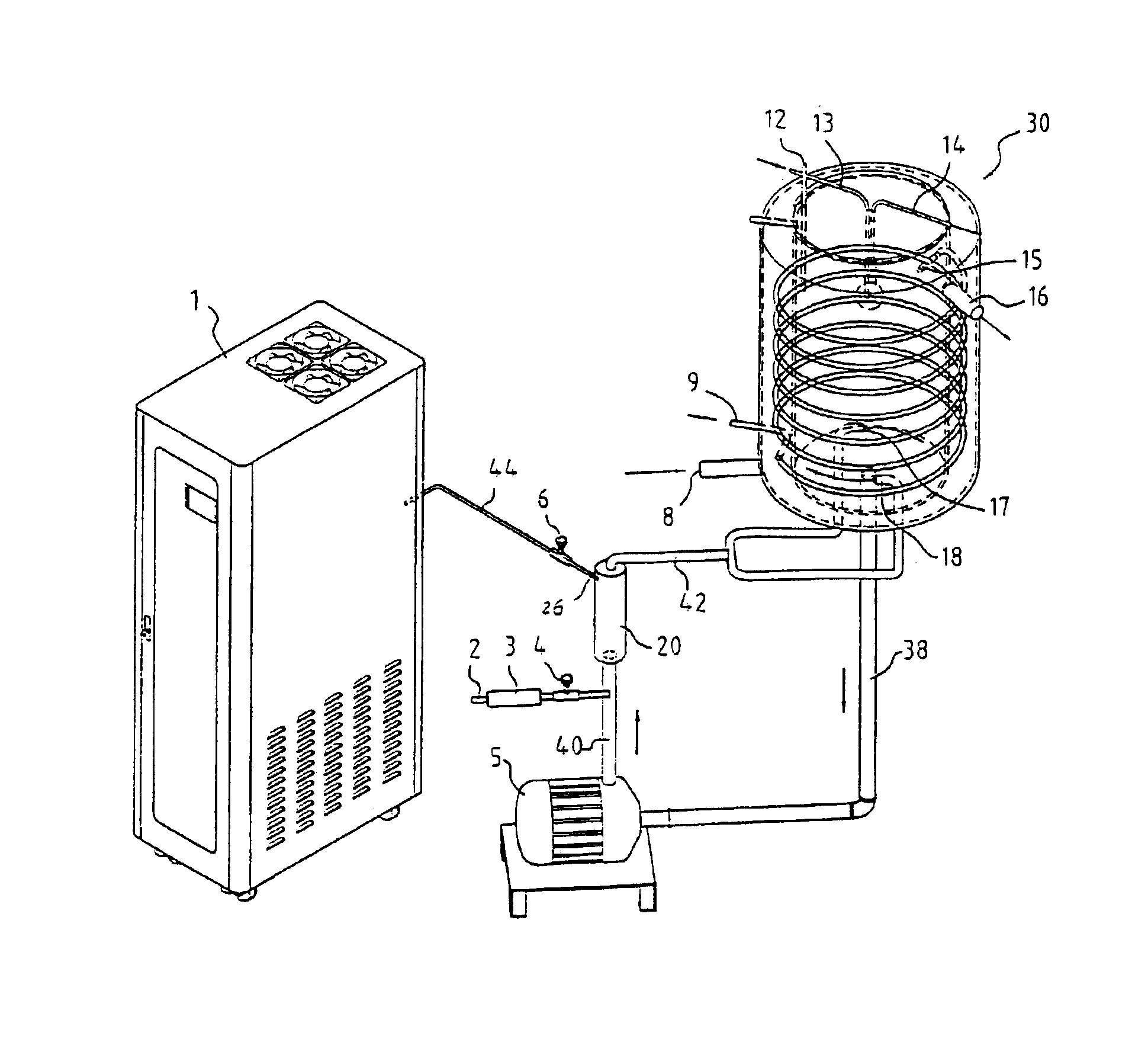
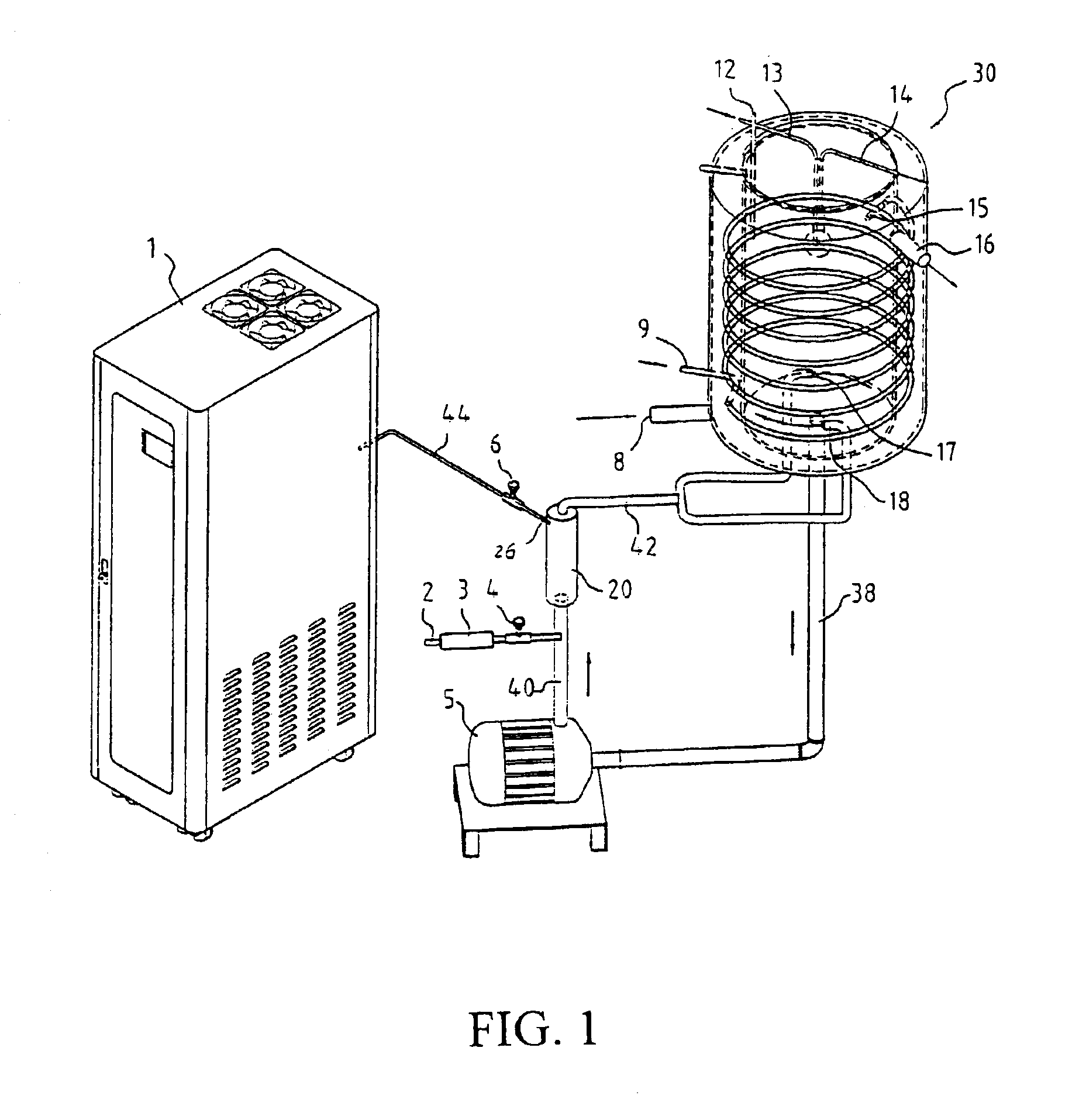
[0020]As shown in FIG. 1, the apparatus according to the present invention comprises primarily a gas generator 1, a mixer 20, a tank enclosure 30, and a pump 5.

[0021]The gas generator 1 is connected to a gas inlet 26 of the mixer 20 by a gas pipe 44. A valve 6 is arranged at the gas inlet 26 of the mixer 20.

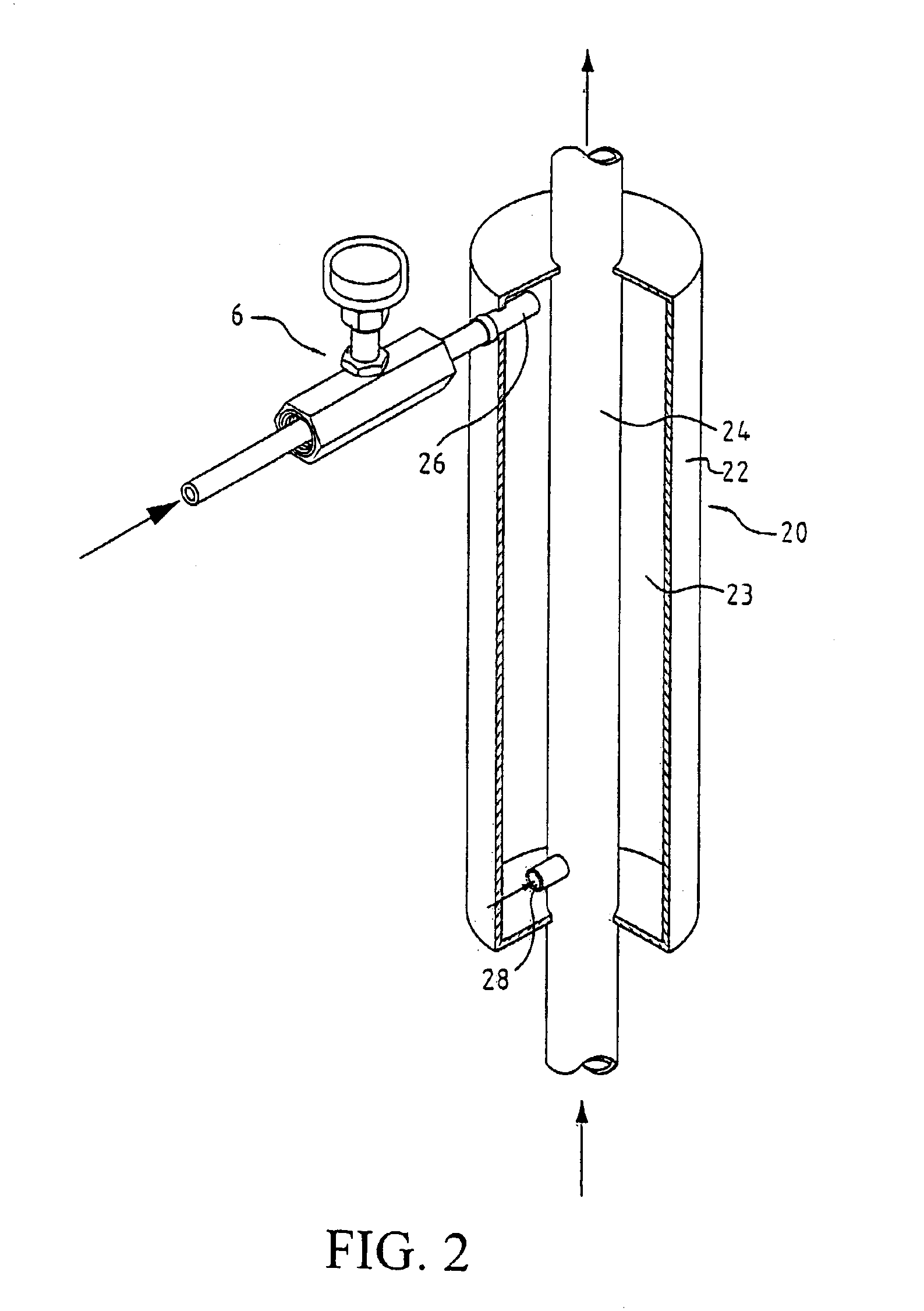
[0022]As shown in FIG. 2, the mixer 20 comprises: a container 22 and a quasi-Venturi tube 24. The container 22 is an axially extended enclosure with one end provided with the gas inlet 26. The gas inlet 26 is further provided with the valve 6 for regulating the flow rate of the incoming gas. The quasi-Venturi tube 24 has one end being a liquid inlet port and the other end being a liquid outlet port, and is axially arranged in the container 22 so that it passes through the container 22 from one end to the o...


PUM

PropertyMeasurementUnit
flow rateaaaaaaaaaa
shapeaaaaaaaaaa
concentrationaaaaaaaaaa

Abstract

An apparatus for effectively dissolving gas into liquid medium to obtain high concentration of gas solution includes a mixer and a tank enclosure, wherein the mixer primarily includes a quasi-Venturi tube and an expansion chamber. During operation, gas is introduced into the liquid in the quasi-Venturi-typed mixer. A valve mounted at the inlet of the mixer is used to regulate the gas flow so that the flow rate of the gas entering the mixer is lower than the rate of the gas drawn into the quasi-Venturi tube. With the gas drawn-in capability of the quasi-Venturi tube, gas can be mixed with the liquid flow through the quasi-Venturi tube under negative pressure and forms small gas bubbles in the liquid. The liquid carrying small gas bubbles flows out of the mixer, and subsequently flows into the tank enclosure and forms a whirlpool therein. As such, the gas bubbles can remain in the liquid for a prolonged time, which helps the gas dissolve in the liquid. The mixing apparatus is applicable for producing high gas concentration of water.

Description

CROSS-REFERENCES TO RELATED APPLICATIONS[0001]This application claims the benefit of Taiwan application serial number 092100087, filed on Jan. 3, 2003, the benefit of which is hereby claimed under 35 U.S.C. Sec. 119(a).STATEMENT REGARDING FEDERALLY SPONSORED RESEARCH OR DEVELOPMENT[0002]Not ApplicableDESCRIPTION[0003]1. Field of Invention[0004]The invention relates to an apparatus for dissolving gas into liquid.[0005]2. Background[0006]In many industrial applications, gas solutions are usually needed. However, most gases cannot easily dissolve in water. Generally, a gas solution would not achieve the desired purpose if the concentration of the gas is too low. Without some special processing procedures, a solution with low gas concentration cannot be used in real application. Therefore, an apparatus for producing high concentration of gas solution is desperately needed in commercial applications. An apparatus for producing gas solution with high concentration can be implemented to di...

Claims


Application Information

Patent Timeline
Patent Type & Authority Patents(United States)
IPC IPC(8): B01J7/00B01J7/02B01F15/00B01F3/04B01F15/06B01F5/00B01J10/00B01F5/10B01F5/04C01B13/10B01F13/00B01F13/06B01F1/00
CPCB01F3/0446B01F5/0413B01F5/106B01F15/066B01J4/002B01J7/02B01J10/002C01B13/10B01F5/0068Y10S261/75B01F13/06B01F2003/04879B01F2003/04886B01F2003/04893B01J2219/00063B01J2219/00078Y10S261/42B01F23/232B01F23/237613B01F23/237612B01F23/23762B01F25/104B01F25/312B01F25/53B01F33/70B01F35/93B01F23/2326
Inventor LIOU
Owner LIOU
Why Eureka
Try Eureka