

Coupling vibration ultrasonic hand piece
a technology of ultrasonic hand pieces and ultrasonic horns, which is applied in the field of complex vibration ultrasonic hand pieces, can solve the problems of increasing the load of the output system of high frequency electric power, generating longitudinal vibration at the horn tip, and difficult handling, so as to reduce the torsional vibration speed of the non-working plane
Active Publication Date: 2005-10-18
STRYKER CORP
View PDF4 Cites 75 Cited by
- Summary
- Abstract
- Description
- Claims
- Application Information
AI Technical Summary
Benefits of technology
The present invention is a complex vibration ultrasonic hand piece that solves the problem of excessive torsional vibration speed on the non-working plane. The invention includes an ultrasonic oscillation mechanism, a vibration conversion mechanism, and a female portion with a working plane. The ultrasonic oscillation mechanism generates an ultrasonic vibration of a predetermined frequency. The vibration conversion mechanism converts the ultrasonic vibration into a composite vibration composed of a longitudinal vibration in the horn central axial direction and a torsional vibration having the horn central axis as fulcrum. The female portion is provided with a working plane for reducing the torsional vibration speed of the non-working plane. The groove portions are sometimes juxtaposed in plurality, and the speed variation mechanism of reciprocating rotation in the female portion is composed of a curved surface body or a spindle. The curved surface body or spindle has a working plane for reducing the torsional vibration speed of the non-working plane. The groove portion may have a predetermined deflection angle, and the torsional vibration attenuation means may be provided between the groove portion and the electrostrictive element of the ultrasonic oscillation mechanism. The vibration conversion mechanism may also include a body detachably interposed between the horn and the ultrasonic oscillation mechanism and a groove portion formed around the body circumferential surface.
Problems solved by technology
For example, in the case of so-called longitudinal vibration where the properties of the vibration element are parallel to the axial direction, it results in the generation of longitudinal vibration at the horn tip.
Therefore, a configuration for obtaining a vertical-torsional composite vibration by composing the vibration element of the vibration mechanism with a longitudinal vibration element and a torsional vibration element may be devised; however, the structure of the ultrasonic oscillation mechanism becomes complicated and heavy, not only making the handling difficult but also increasing the load of the output system of high frequency electric power and creating problems not only in respect of manufacturing cost but also running cost, and therefore is not composed practical actually.
In addition, conventionally, a drill has been used for cutting hard tissues of a living body, and it is feared that nerves and vessels be caught by the drill rotation in an area where nerves, vessels or others are entangled complicatedly.
Therefore, it can not be used in the vicinity of nerve or vessel, and cases where the operation was composed impossible were not rear.
Consequently, it is necessary to secure the safety by attenuation limitation of the cutting force as for the periphery of the target area, and processing only the target area with a predetermined cutting force.
Method used
View moreImage
Smart ImageViewing Examples

Examples
first embodiment
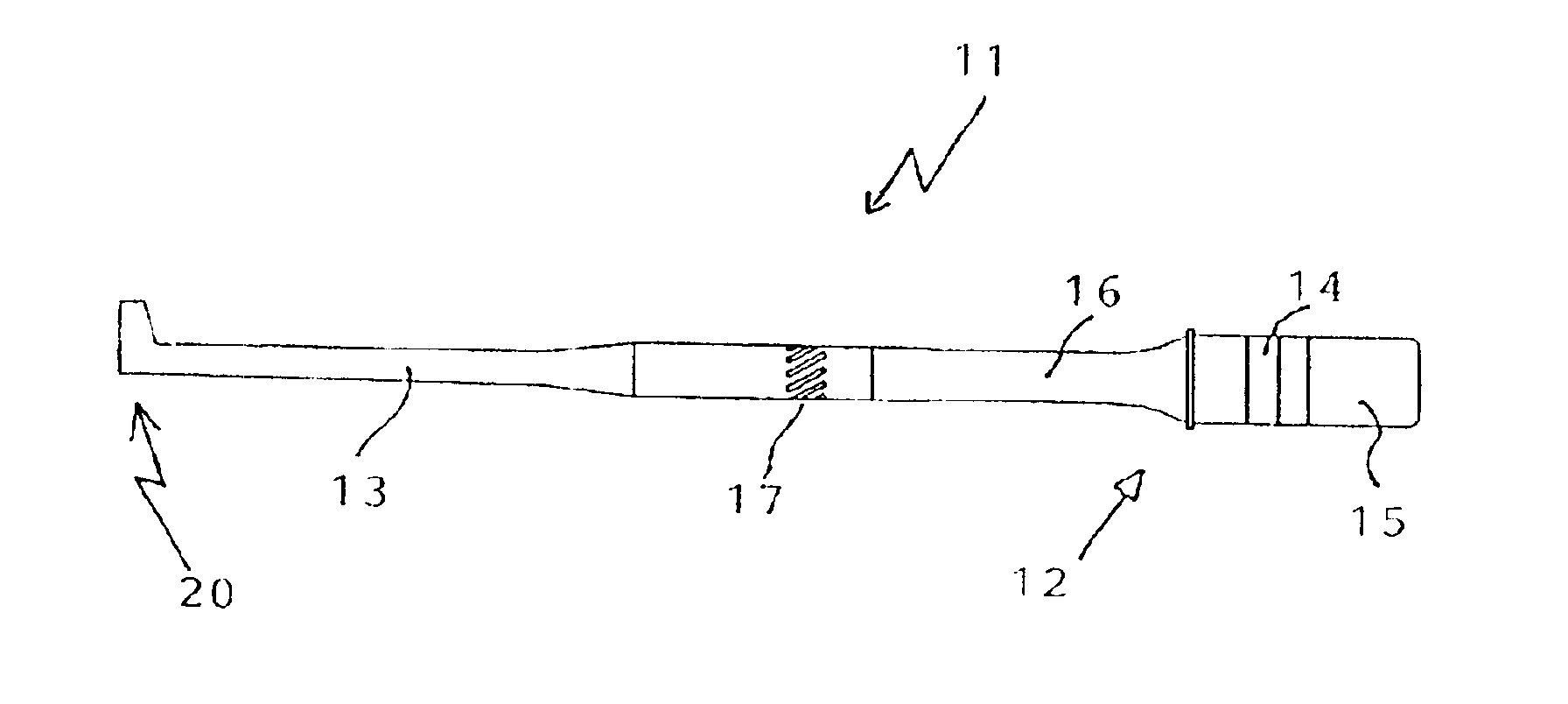
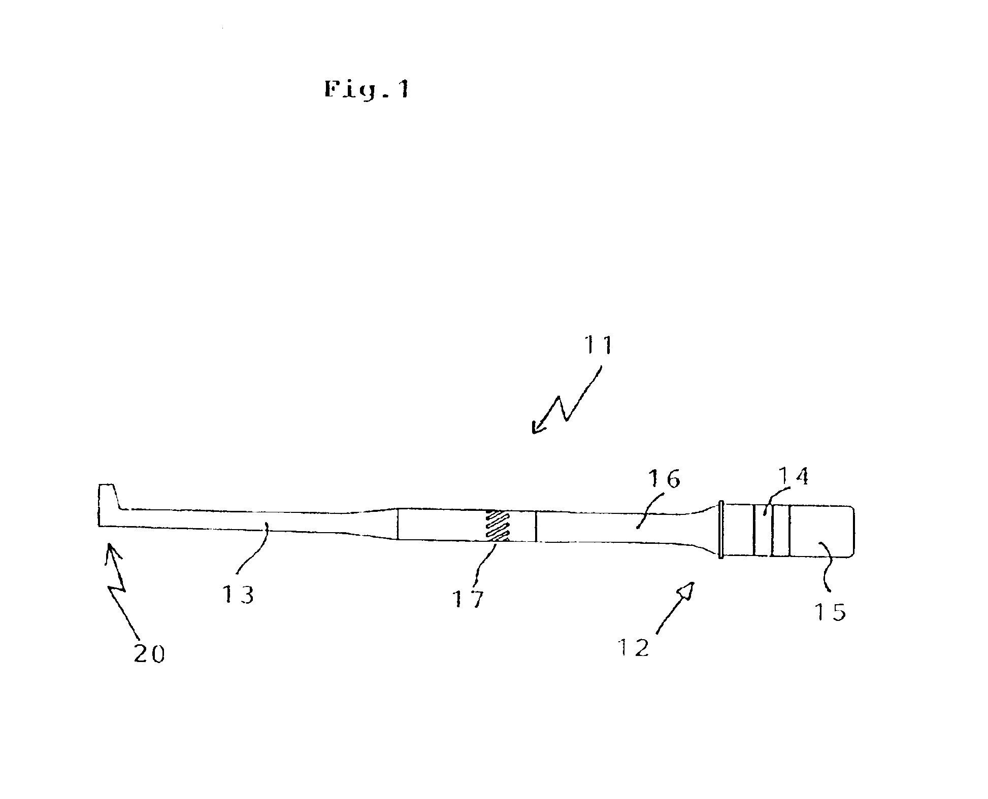
[0024]FIG. 1 is a side view of the ultrasonic hand piece ;
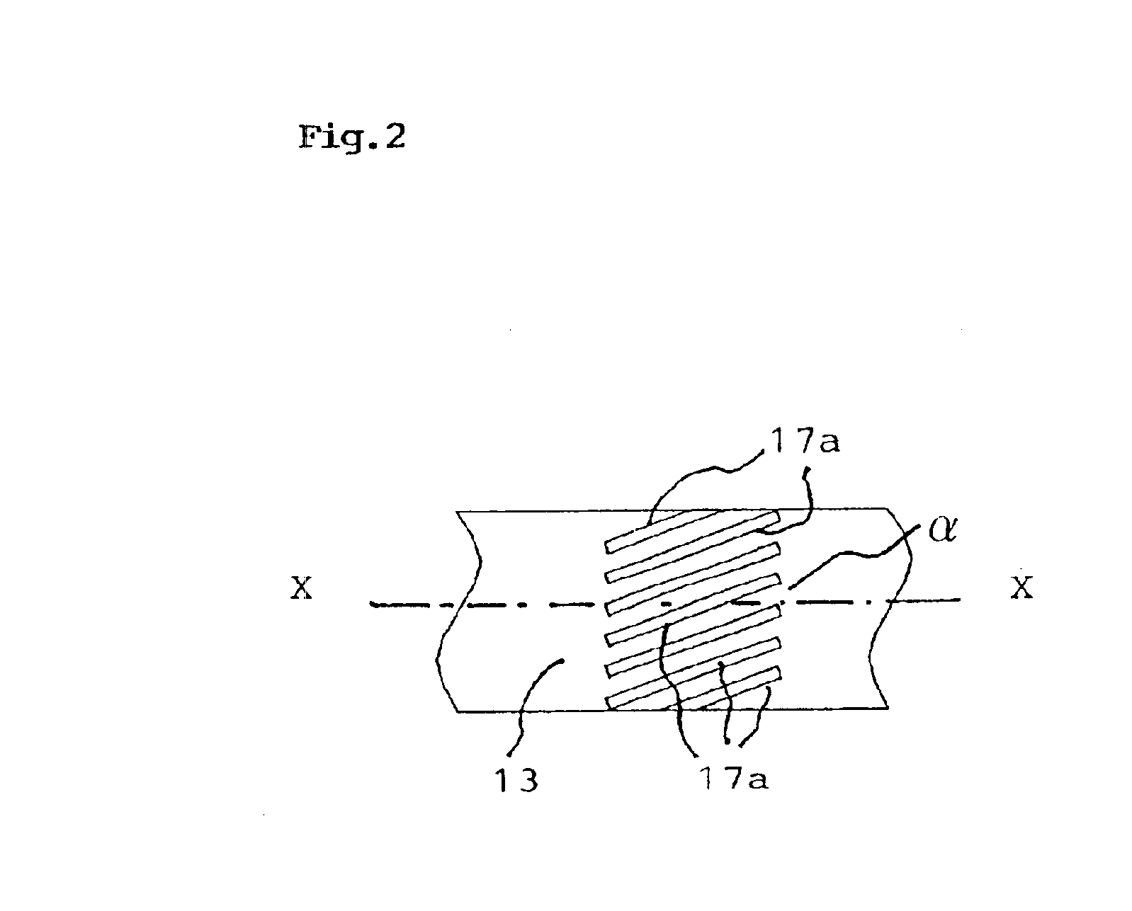
[0025]FIG. 2 is a enlarged view of essential parts of FIG. 1;
[0026]FIG. 3 is an enlarged view of a female portion having a speed variation mechanism;
[0027]FIG. 4 is an enlarged view of the female portion according to another embodiment;
[0028]FIG. 5 is an enlarged view of the female portion according to another embodiment;
[0029]FIG. 6 is an enlarged view of the female portion according to another embodiment;
second embodiment
[0030]FIG. 7 is a partially omitted side view of the ultrasonic hand piece showing a second embodiment;
third embodiment
[0031]FIG. 8 is a side view of the ultrasonic horn ;
Login to View More PUM
 Abstract
Problems to be SolvedSurgical operation or others excellent in operability, safety, operation efficiency and precision are realized by outputting a vertical-torsional composite vibration through conversion processing of the longitudinal vibration from an ultrasonic oscillation mechanism and reducing the displacement speed of the non-working plane in a female portion less than the speed of the working plane.Means to Solve the ProblemA configuration, comprising an ultrasonic oscillation mechanism composed of a longitudinal vibration element, a backing plate and a front plate for generating an ultrasonic vibration, a horn coupled with the ultrasonic oscillation mechanism for amplifying the vibration transmitted from said ultrasonic oscillation mechanism, a vibration conversion mechanism for converting the vibration transmitted from said ultrasonic oscillation mechanism into a composite vibration composed of a longitudinal vibration in the horn central axial direction and a torsional vibration having the horn central axis as fulcrum, and a female portion provided with a working plane and disposed at said horn tip, wherein said ultrasonic oscillation mechanism is composed of one or more groove portions formed on the circumferential surface of the horn or said backing plate, and a speed variation mechanism of torsional vibration in said composite vibration is formed in the female portion, in order to reduce the reciprocating rotation speed of the non-working plane less than the speed of the working plane.
Description
DETAILED DESCRIPTION OF THE INVENTION[0001]1. Field of the Invention[0002]The invention of the present Application concerns a complex vibration ultrasonic hand piece, and more particularly, a complex vibration ultrasonic hand piece for reducing the reciprocating rotation speed of non working plane less than the speed of the working plane by generating a composite vibration composed of a longitudinal vibration in the horn central axial direction and a torsional vibration having the horn central axis as a fulcrum at a horn tip by converting the longitudinal vibration from a vibration source and, on the other hand, by forming a speed variation mechanism of torsional vibration in the composite vibration at the female portion of the horn tip.[0003]2. Detailed Description of the Prior Art[0004]Conventionally, the complex vibration ultrasonic hand piece has been used as one of various instruments of operation in the surgery domain, or as apparatus for processing of a variety of materials.[...
Claims
Login to View More Application Information
Patent Timeline
 Patent Type & AuthorityPatents(United States)
IPC IPC(8): B06B3/00A61B18/00
CPCB06B3/00A61B2017/320096A61B2017/320098
InventorSATOU, YUICHIROUOTA, HIDEFUMI
OwnerSTRYKER CORP