Apparatus and method for testing optical transceivers

a technology of optical transceivers and apparatuses, applied in the field of systems, apparatus and methods for testing optical transceivers, can solve problems such as introducing errors and aberrations into the optical system, reducing the size of detectors, and reducing the size of optical transceivers

Inactive Publication Date: 2005-10-18
II VI DELAWARE INC
View PDF4 Cites 28 Cited by
  • Summary
  • Abstract
  • Description
  • Claims
  • Application Information

AI Technical Summary

Benefits of technology

[0013]The mirror assembly is also connected with a micrometer that can adjust the position of the mirror with respect to the lens of the port in order to correctly position the mirror at the conjugate position from the optical fiber facet. The conjugate position from the optical fiber is the same as the laser position in a transmitter port, or the detector position in a receiver port. This further provides the ability to determine if the lens is within the focal specification of the lens of the port being tested.

Problems solved by technology

This is particularly true as the size of detectors decreases, often for cost reasons.
In spite of the advantages afforded by these small the small size and the embedded position of the optical components, the size of the optical transceiver can also present several problems.
Deviations of the surface curvature of the integrated lens from the design curvature of the integrated lens, due to the molding process or pressing of the molded lens element into the housing of the optical transceiver, can introduce errors and aberrations into an optical system.
Other surface and volume degradations such as scratches, digs, and bubbles introduced in the molding process or as a result of placement and fixing of the molded lens element inside the port also reduce the optical efficiency of the coupling element in an optical system.
The combined effect of these and other errors lessen the overall quality of a particular optical transceiver.
In small form factor optical transceivers, however, it is difficult and cumbersome to use standard optical equipment to perform the usual optical surface measurements because of the small geometry of the optical transceiver.
In particular, the embedded nature of the lens in the optical transceiver makes a traditional analysis of the lens element impractical and costly.

Method used


Image

  • Apparatus and method for testing optical transceivers
  • Apparatus and method for testing optical transceivers
  • Apparatus and method for testing optical transceivers

Examples


Embodiment Construction

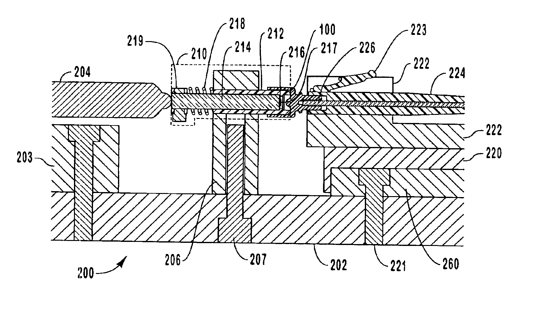
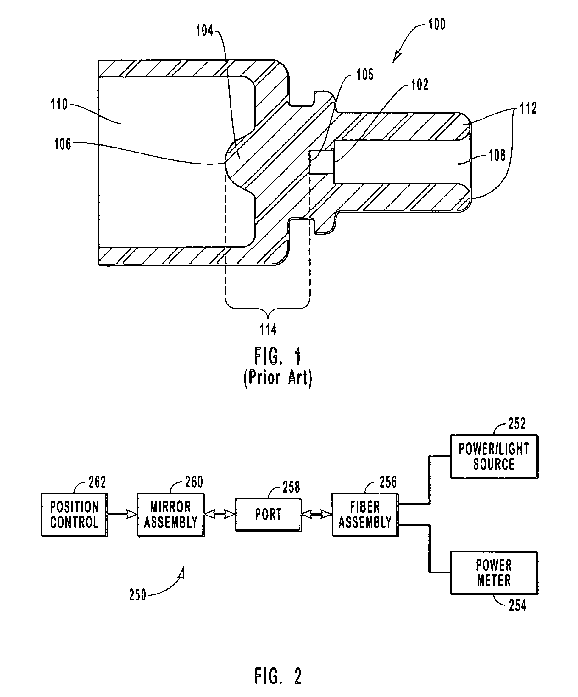
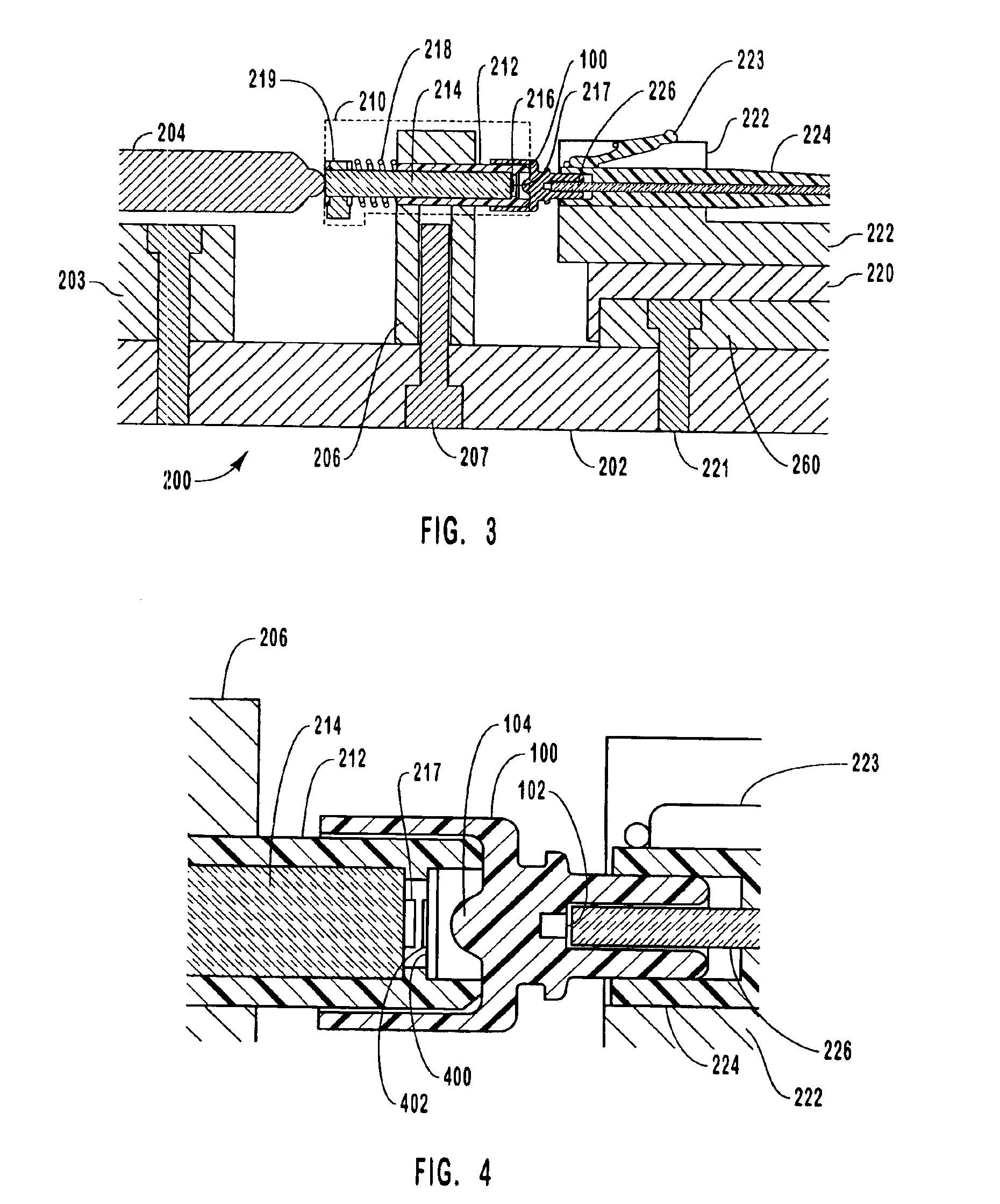
[0022]Small form factor optical transceivers that contain small optical elements are preferred in optical communication networks for their small size, their low cost, and the integrated nature of the optical port design. In particular, these optical transceivers are able to incorporate small lenses that are used, for example, to couple laser or source light into transmission fibers (a transmitter optical port), as well as image the output of an optical fiber onto a detector (a receiver optical port).

[0023]Efficient coupling of a source light into an optical transmission fiber achieves adequate transmission power with minimum source strength. Furthermore, it becomes increasingly important to efficiently image the output of a fiber onto a detector as the physical size of the detector decreases. As previously stated, the small size of the optical transceivers, the embedded nature of the optical elements, the difficulty in measuring the optical quality of the embedded lens, and the like...


PUM

PropertyMeasurementUnit
optical qualityaaaaaaaaaa
forceaaaaaaaaaa
resilientaaaaaaaaaa

Abstract

Systems, apparatus and methods for testing the optical quality of optical transceivers or ports. A port tester is provided that is used to quantitatively measure the optical quality of ports. A port is inserted in the port tester between a mirror assembly and a fiber assembly. A mirror included in the mirror assembly is positioned in or near a focal plane of the port lens. A test light signal is directed through the port from the optical fiber and is reflected back through the port by the mirror. The power of the reflected test signal is compared to a control signal and the comparison between these signals is indicative of the optical quality of the port. The fiber assembly is retractable such that a new port can be mounted in the port tester and tested.

Description

CROSS-REFERENCE TO RELATED APPLICATIONS[0001]This application claims the benefit of U.S. Provisional Application No. 60 / 422,239, filed Oct. 30, 2002 and entitled APPARATUS AND METHOD FOR TESTING OPTICAL TRANSCEIVERS, which is hereby incorporated by reference.BACKGROUND OF THE INVENTION[0002]1. The Field of the Invention[0003]The present invention relates to systems, apparatus and methods for testing optical transceivers. More particularly, the present invention relates to apparatus and methods for testing small form factor optical transceivers with optical components that are an integral part of the optical transceivers.[0004]2. Background and Relevant Art[0005]Fiber optic networks often include a transmission side and a receiver side. On the transmission side, it is important that the light be efficiently coupled into the transmission fiber in order to achieve adequate transmission power with minimum laser output strength. On the receiver side, it is important to efficiently image ...

Claims


Application Information

Patent Timeline
Patent Type & Authority Patents(United States)
IPC IPC(8): G01N21/00G01L17/00
CPCG01L17/00
Inventor FARR, MINAFUHRMANN, ROBERT
Owner II VI DELAWARE INC
Why Eureka
Try Eureka