Switching power supply apparatus

a power supply and switch technology, applied in the direction of electric variable regulation, process and machine control, instruments, etc., can solve the problems of transformers prone to magnetic saturation, complicated control circuits of switches, etc., to improve apparatus, improve efficiency, and reduce copper loss.

Inactive Publication Date: 2005-10-18
FIDELIX
View PDF6 Cites 21 Cited by
  • Summary
  • Abstract
  • Description
  • Claims
  • Application Information

AI Technical Summary

Benefits of technology

[0015]However, to improve the efficiency is an eternal theme for the engineers in the power supply apparatus field, therefore, the present invention further improves the apparatus in U.S. Pat. No. 6,304,460 from this point of view. That is to say, in the apparatus of U.S. Pat. No. 6,304,460, the copper loss of the input winding 101b and the primary winding 101a is still large; therefore the present invention has its purpose to provide a power supply apparatus where the copper loss is further reduced to obtain a better efficiency.
[0017]As mentioned above, the convention apparatus shown in U.S. Pat. No. 6,304,460 has an excellent benefits from the point of view that the copper loss and the iron loss are small and the apparatus can be made compact. However, it has a problem that the control circuit for switches is very complicated. The present invention has for its second purpose to provide a power supply apparatus where a normal controlling IC for controlling a switching power apparatus can be used to control the switches and the DC magnetic flux can be reduced as well as the apparatus in U.S. Pat. No. 6,304,460.
[0019]In order to achieve the first purpose, the power supply apparatus according to the present invention is constituted to provide a tap in the primary winding and to connect the tap to the minus side of the input winding. According to this construction, the copper loss and the iron loss can be further reduced and therefore a better efficiency can be obtained.
[0020]Further, in order to achieve the second and third purposes, the power supply apparatus according to the present invention provides an improvement of the apparatus disclosed in U.S. Pat. No. 6,304,460, where the surge voltage clamping circuit is elaborated and the circuit construction is simplified so that the improvement can be applied a converter, which is able to work with a general controlling IC for controlling switching apparatus, i.e. fryback converter, boost converter, forward converter and irregular fryback converter. As a result, it becomes easier to control the switching element(s) of the apparatus and the gap between the cores can be made narrower or no gap is necessary. Therefore, the number of turns of windings can be made fewer so that the copper loss and the iron loss are reduced and thus a higher efficiency can be achieved.

Problems solved by technology

However, it has a problem that the control circuit for switches is very complicated.
Furthermore, a converter, such as fryback converter, boost converter, forward converter, and irregular fryback converter, that operates in a condition that the magnetic flux is unbalanced, has a problem that the transformer is apt to have a magnetic saturation when the apparatus is applied to deal with a large amount of electric power.

Method used


Image

  • Switching power supply apparatus
  • Switching power supply apparatus
  • Switching power supply apparatus

Examples


first embodiment

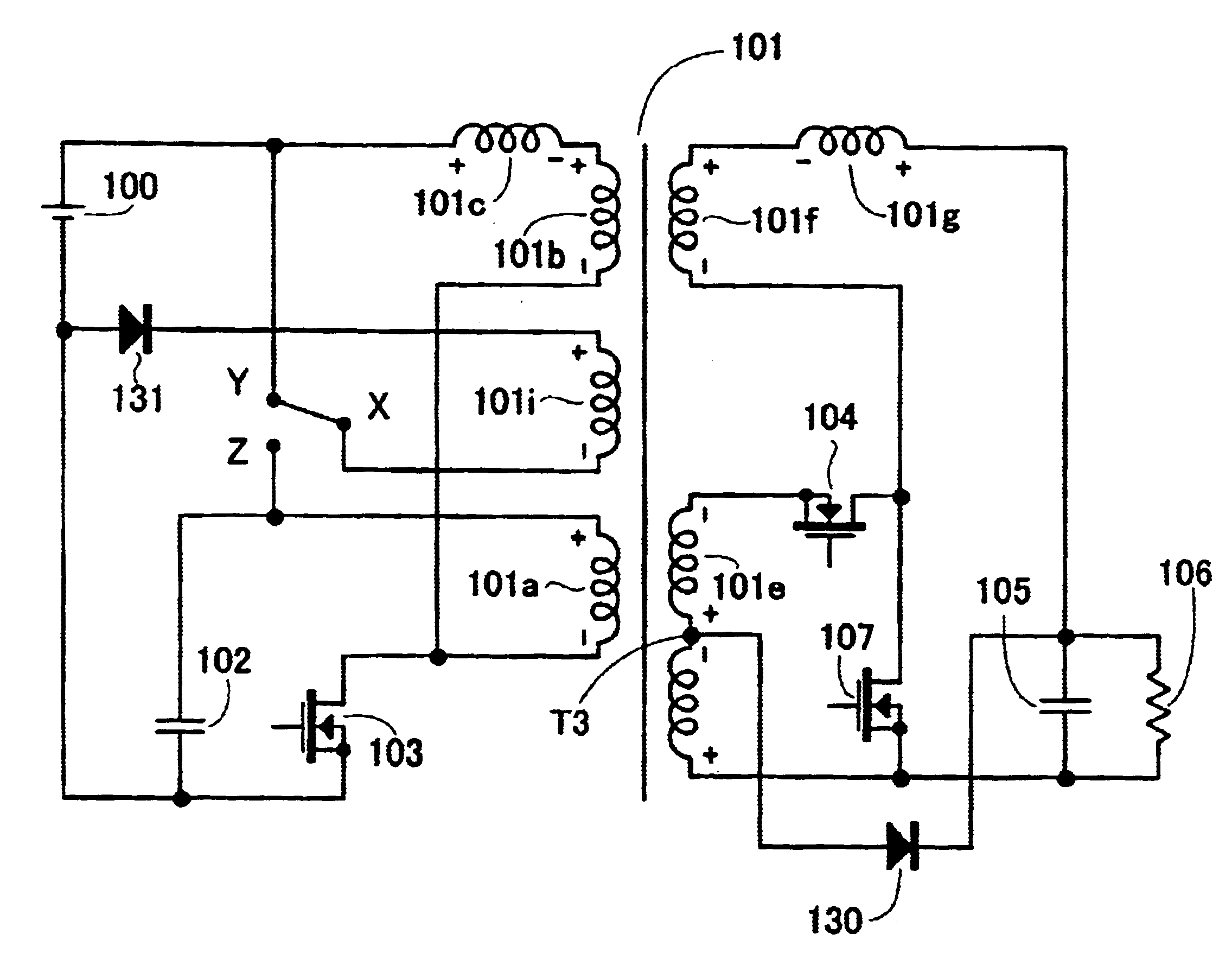
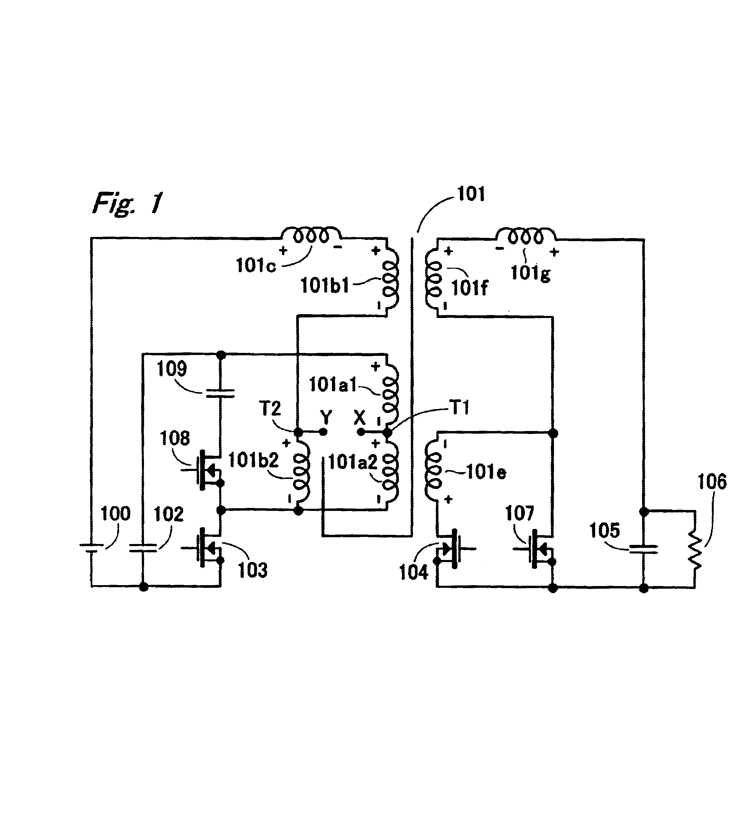
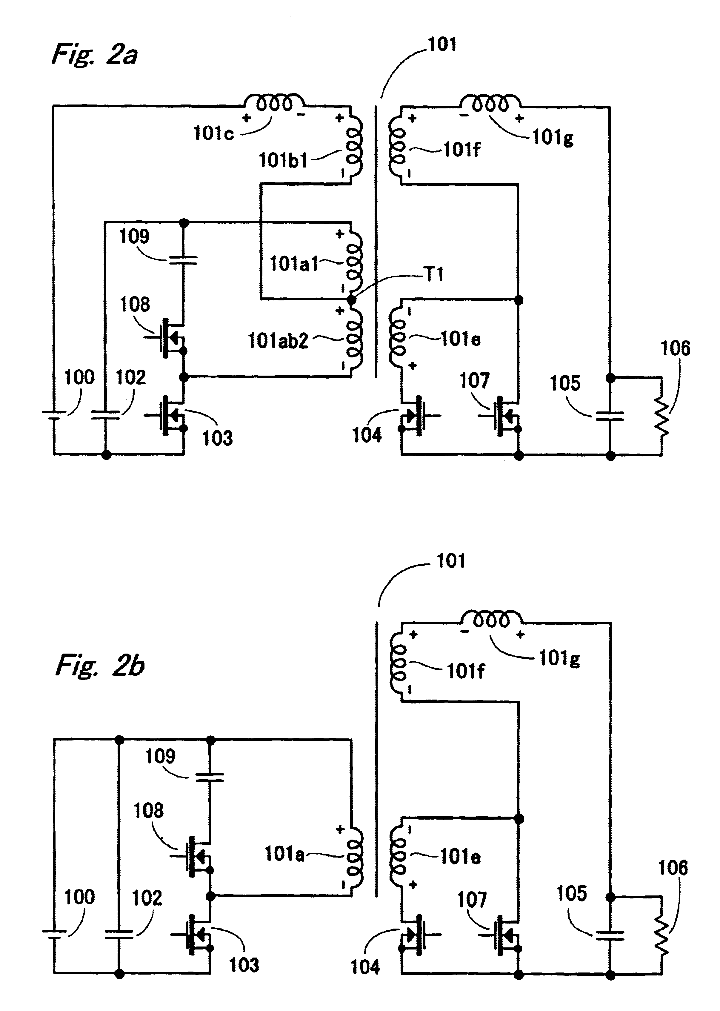
[0099]FIG. 2a is a circuit diagram showing the present invention, where the points X and Y in FIG. 1 are connected together and the other portions are adjusted. That is to say, the parallel connected portions of the primary winding 101a2 and the input winding 101b2 are referred as 101ab2. The electric current coming from the input winding 101b is injected to the intermediate tap T1 provided in the primary winding. It should be noted that a high frequency current is apt not to flow in the input current by an arrangement that the intermediate tap T1 is provided just the half point of the primary winding and the number of turns of the input winding 101b1 becomes a half of that of the input winding 101b of the conventional apparatus in FIG. 30.

[0100]In this manner, the present invention is constituted such that the intermediate tap T1 is provided between the AC earth point caused by the bypass capacitor 102, i.e. the plus side of the primary winding 101a, and the AC switching point, i.e...

second embodiment

[0103]In the second embodiment, in order to use a general control IC for switching power supply apparatus, the sub switch 108 and the clamping capacitor 109 are removed, and the rectifying switch 107 is substituted by a capacitor 107a and the rectifying switch 104 is also substituted by a diode 104a, as shown in FIG. 3a. It is very important that the rectifying switch 107 is changed to the capacitor 107a. The reason is; if the rectifying switch 107 is used there, the sub switch 108 and the clamping capacitor cannot be removed, because if the switches 107 and 108 are removed, the surge voltage generated in the primary winding 101a cannot be clamped, so that abnormal voltage would be caused and then an appropriated operation could not be conducted.

[0104]In the apparatus shown in FIG. 3a, when the duty ratio is 0.5, the magnetic flux canceling winding 101f works out to cancel the DC magnetic flux generated in the core of the transformer 101 by an arrangement that the number of turns of...

fourth embodiment

[0111]Here, how to drive the sub switch 108 is an issue. It may be possible to drive the sub switch with the aid of a high side driver, however, such a driver is expensive and when the input voltage is high, the power consumption when no load is applied becomes great. Therefore, in the present application, an additional winding 101h is provided on the transformer 101h, so that the sub switch 108 is driven by the winding 101h.

[0112]In the fourth embodiment, it is arranged such that when the main switch 103 becomes OFF, the sub switch 108 is made ON with a delay of dead time, which is generated by a resistance 112 and a capacitor 113. To make the sub switch 108 OFF, a timer circuit constituted of a resistance 114 and a capacitor 115 is provided, that works to make compulsorily the gate of the sub switch 108 OFF by a transistor 116 after a given time has passed.

[0113]It is not difficult to make the main switch 103 ON after the sub switch 108 becomes OFF with a dead time. Such an IC ma...


PUM


Abstract

A switching power supply apparatus which has an input power source; a transformer having a primary winding, a secondary winding, an input winding and a magnetic flux canceling winding being connected to the secondary winding in series; a main switch for switching an electric current going through the primary winding; a bypassing capacitor for bypassing the primary winding; a sub switch for clamping a surge voltage, which is generated in the primary winding; a clamping circuit constituted of the sub switch and a clamping capacitor; a first rectifying switch for rectifying an electric current going through the secondary winding and the magnetic flux canceling winding during when the main switch is being OFF; a second rectifying switch for rectifying an electric current going through the magnetic flux canceling winding during when the main switch is being ON; and a smoothing capacitor for smoothing an electric current going through the magnetic flux canceling winding; and the magnetic flux canceling winding is provided in a direction that is opposite to a direction of a magnetic flux generated by the input winding, the primary winding and the secondary winding; and wherein an intermediate tap is provided in the primary winding so as to supply an electric current coming from the input power source to the main switch via the input winding and the intermediate tap.

Description

BACKGROUND OF THE INVENTION[0001]1) Field of the Invention[0002]The present invention relates to switching power supply apparatuses; particularly, relates to apparatuses where a DC magnetic flux component, which is generated in switching power supply apparatuses operating in such a condition that the magnetic flux generated in a transformer is unbalanced, is cancelled with the aid of output current or input current of the power supply apparatus, so that the efficiency of the apparatus is improved.[0003]2) Related Art Statement[0004]Such a switching power supply apparatus where a direct magnetic flux component generated in switching transformers is cancelled is disclosed in U.S. Pat. No. 6,304,460.[0005]FIG. 30 shows an example of the power supply apparatus disclosed in U.S. Pat. No. 6,304,460. The circuit shown in FIG. 30 corresponds to that in FIG. 35b of U.S. Pat. No. 6,304,460. In order to make the following explanation easy the position of the windings are modified in FIG. 30, h...

Claims


Application Information

Patent Timeline
Patent Type & Authority Patents(United States)
IPC IPC(8): H02M3/335H02M3/24H02M3/28
CPCH02M3/33569H02M3/33576H02M2001/0093H02M1/0093H02M3/33571H02M3/01
Inventor NAKAGAWA, SHIN
Owner FIDELIX
Why Eureka
Try Eureka