Optical recording medium with recording marks having different states, and method of recording using the optical recording medium

a recording medium and optical recording technology, applied in the field of optical recording medium and method, can solve the problems of difficult to achieve five or more multi-level recording by changing the laser power, short irradiation time, and worsening reading quality, and achieve the effect of high read accuracy

Inactive Publication Date: 2005-10-18
TDK CORPARATION
View PDF14 Cites 2 Cited by
  • Summary
  • Abstract
  • Description
  • Claims
  • Application Information

AI Technical Summary

Benefits of technology

[0013]The present invention has been made in order to further study the above technology. Accordingly, an object of the present invention is to provide an optical recording medium, which can achieve multi-stage (multi-level) and high read-accuracy multi-level recording by setting a power of laser beam to a predetermined range.

Problems solved by technology

In the above multi-level recording, a laser beam is irradiated at multiple-stage power in recording; for this reason, in particular, when the power of laser beam gradually becomes large, a problem has arisen such that a signal quality is worsened in reading.
In fact, it is very difficult to achieve five stages or more multi-level recording by the method of changing a laser power.
The above optical recording method is a concept quite different from the conventional laser beam irradiation, and probably includes an extremely short irradiation time.

Method used


Image

  • Optical recording medium with recording marks having different states, and method of recording using the optical recording medium
  • Optical recording medium with recording marks having different states, and method of recording using the optical recording medium
  • Optical recording medium with recording marks having different states, and method of recording using the optical recording medium

Examples


example 1

[0085]Using three kinds of laser beams (individually having reference power 10 mW, 11 mW and 12 mW) satisfying the above three conditions (1) to (3), seven stage irradiation time was set, and thereafter, multi-level recording was carried out.

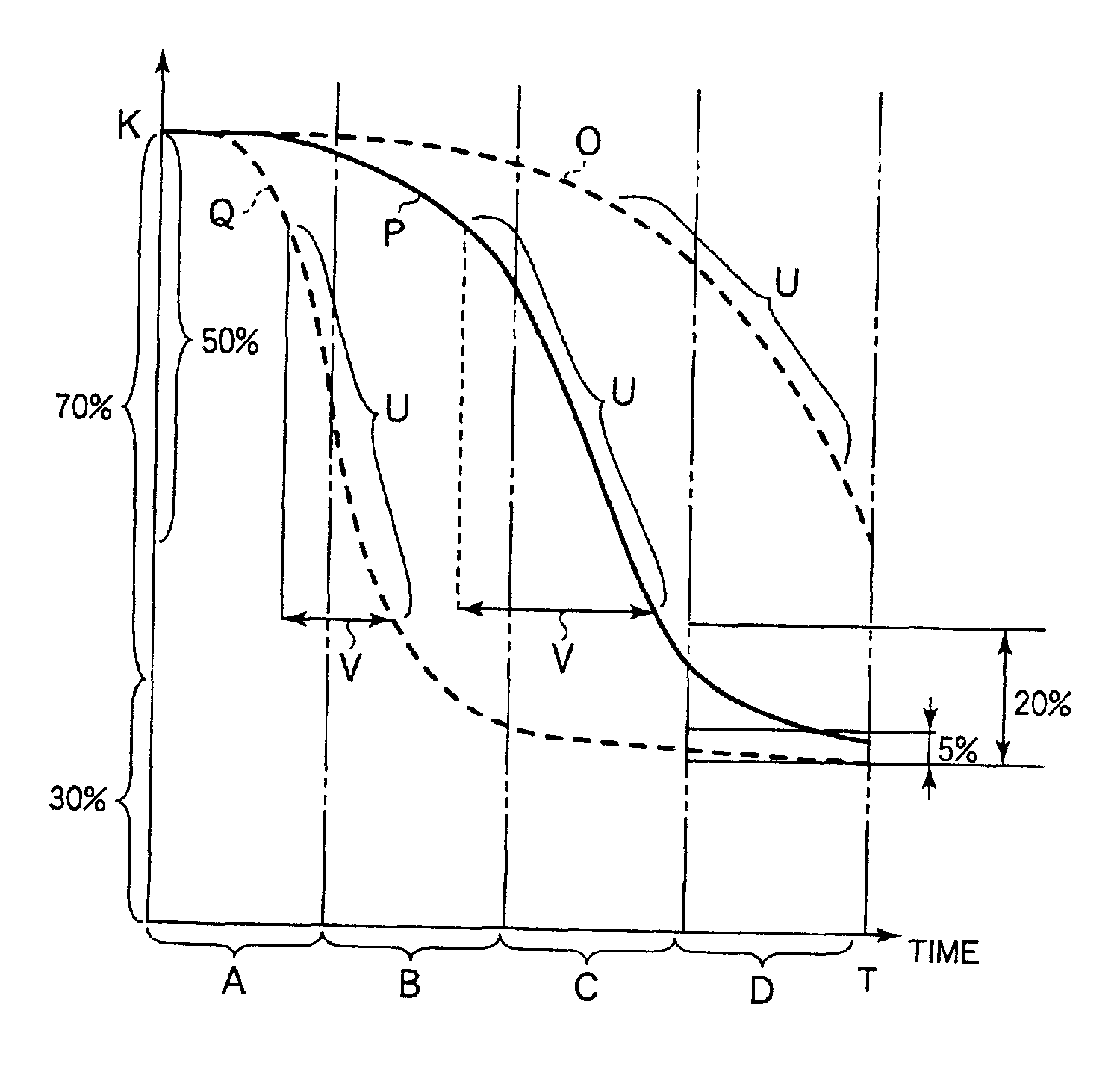
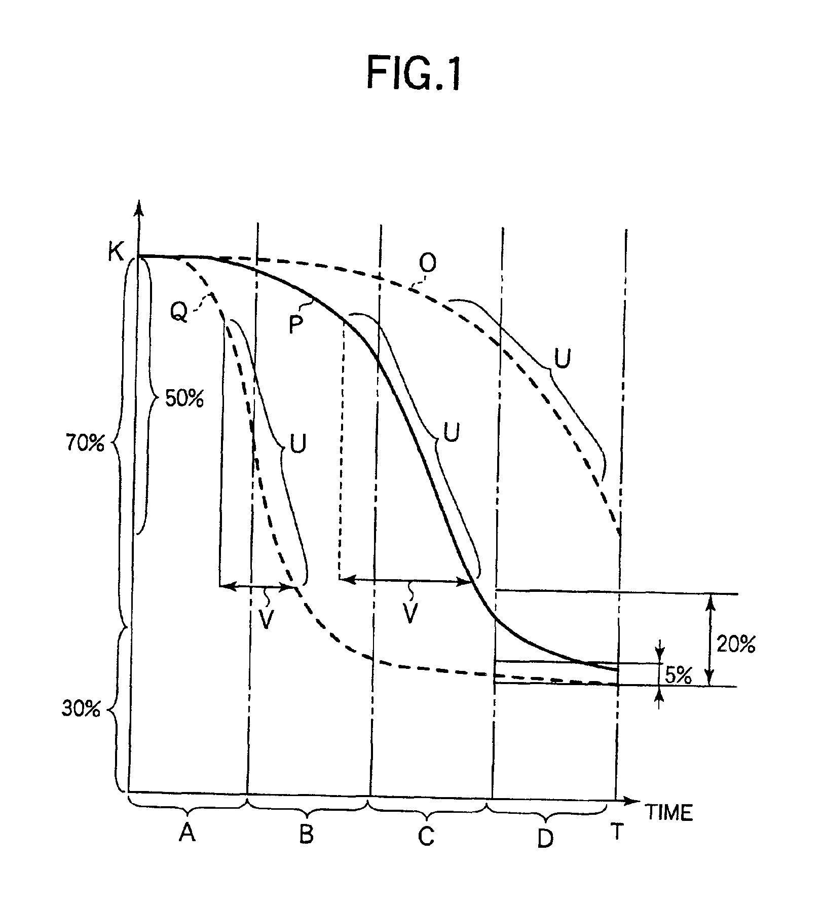
[0086]As a result, it was possible to securely read a recording mark written by each reference power. Further, the signal jitter value was preferable. In FIG. 6, there is shown a time change (solid lines A, B and C) of optical reflectance in the case where a laser beam having each reference power is irradiated to the virtual recording cell over the entire allowable irradiation time.

[0087]As shown in FIG. 6, in all laser beams, the optical reflectance was finally reduced more than 70% of the initial reflectance K. In the termination area ¼ section of the allowable irradiation time, the change of reflectance properly converged, and then, an area suitable for recording was secured for a relatively long time. It can be seen that this satisfies the a...

example 2

[0088]Using a laser beam (having reference power 9 mW), which satisfies the above conditions (1) and (3) but does not satisfy the above condition (2), seven stage irradiation times were set, and thereafter, multi-level recording was carried out.

[0089]As a result, it was possible to securely read a recording mark written by each reference power. Further, the signal jitter value was slightly inferior to the Example 1. In FIG. 6, there is shown a time change (chain line D) of optical reflectance in the case where a laser beam having each reference power is irradiated to the virtual recording cell over the entire allowable irradiation time.

[0090]As shown in FIG. 6, in all laser beams, the optical reflectance was finally reduced more than 70% of the initial reflectance K. However, in this case, the change of optical reflectance is large in the termination area ¼ section of the allowable irradiation time; as a result, the irradiation time corresponding to the area suitable for recording w...

example 3

[0091]Using a laser beam (having reference power 13 mW), which satisfies the above conditions (1) and (2) but does not satisfy the above condition (3), seven stage irradiation times were set, and thereafter, multi-level recording was carried out.

[0092]As a result, it was possible to securely read a recording mark written by each reference power. Further, the signal jitter value was slightly inferior to the Example 1. In FIG. 6, there is shown a time change (two-dotted chain line E) of optical reflectance in the case where a laser beam having each reference power is irradiated to the virtual recording cell over the entire allowable irradiation time.

[0093]As shown in FIG. 6, in all laser beams, the optical reflectance was finally reduced more than 70% of the initial reflectance K. However, in this case, the change of optical reflectance is small in the termination area ¼ section of the allowable irradiation time, and the change of reflectance converged relatively earlier. As a result,...


PUM

PropertyMeasurementUnit
optical reflectanceaaaaaaaaaa
reflectanceaaaaaaaaaa

Abstract

An optical recording medium having a higher improved read accuracy is disclosed. In the case of irradiating a laser beam to an optical recording medium including an optical reflective layer and a recording layer so as to record information therein, in the recording layer, a virtual recording cell having an arbitrary unit length and a unit width perpendicular to the unit length is continuously defined. In the case where the laser beam is irradiated to the virtual recording cell over the entire allowable irradiation time T securable to one virtual recording cell, a reference power of the laser beam is preset so that an optical reflectance of the virtual recording cell can be reduced more than 50% with respect to the initial reflectance. Further, the laser beam having the preset reference power is irradiated to the virtual recording cell in a state that an irradiation time is modulated into five stages or more, and thereby, a recording mark giving five stages or more different optical reflectance to the virtual recording cell can be formed.

Description

BACKGROUND OF THE INVENTION[0001]1. Field of the Invention[0002]The present invention relates to an optical recording medium and method, which record information by irradiating a laser beam to a recording layer so as to form a recording mark, and in particular, to a technology of forming a plurality of recording marks having different state so as to record a data at a multi-level.[0003]2. Description of the Related Art[0004]In a conventional optical recording medium, a method has been employed such that a data is recorded by changing a length of read signal (i.e., a length of reflection signal modulation section). On the contrary, the following method has been frequently studied, more specifically, a plurality of data is recorded to each signal having the same length by changing a depth of the read signal (i.e., a modulation degree of reflection signal) at multiple stages.[0005]According to the above optical recording method, as compared with the case where a binary data is merely r...

Claims


Application Information

Patent Timeline
Patent Type & Authority Patents(United States)
IPC IPC(8): G11B7/013G11B7/0045G11B7/125G11B7/00G11B7/244G11B7/126G11B7/1267G11B7/24
CPCG11B7/00455G11B7/126G11B7/1267G11B7/24085G11B7/24088
Inventor TSUKAMOTO, SYUJI
Owner TDK CORPARATION
Why Eureka
Try Eureka