Radio receiver having a variable bandwidth IF filter and method therefor

a radio receiver and variable bandwidth technology, applied in the field of radio receivers, can solve the problems of degrading the signal quality, affecting the signal quality, and even completely replacing the desired station signal,

Inactive Publication Date: 2005-10-18
NORTH STAR INNOVATIONS
View PDF11 Cites 8 Cited by
  • Summary
  • Abstract
  • Description
  • Claims
  • Application Information

AI Technical Summary

Problems solved by technology

When the received FM signal strength is weak, it may become difficult to have good stereo separation due to excessive noise effects.
Also, interference from an adjacent station (typically about 200 KHz away from the desired station) will degrade the signal quality or even completely replace the desired station signal if the interfering signal is very strong due to the capture effect of the nonlinear demodulation process.

Method used


Image

  • Radio receiver having a variable bandwidth IF filter and method therefor
  • Radio receiver having a variable bandwidth IF filter and method therefor
  • Radio receiver having a variable bandwidth IF filter and method therefor

Examples


Embodiment Construction

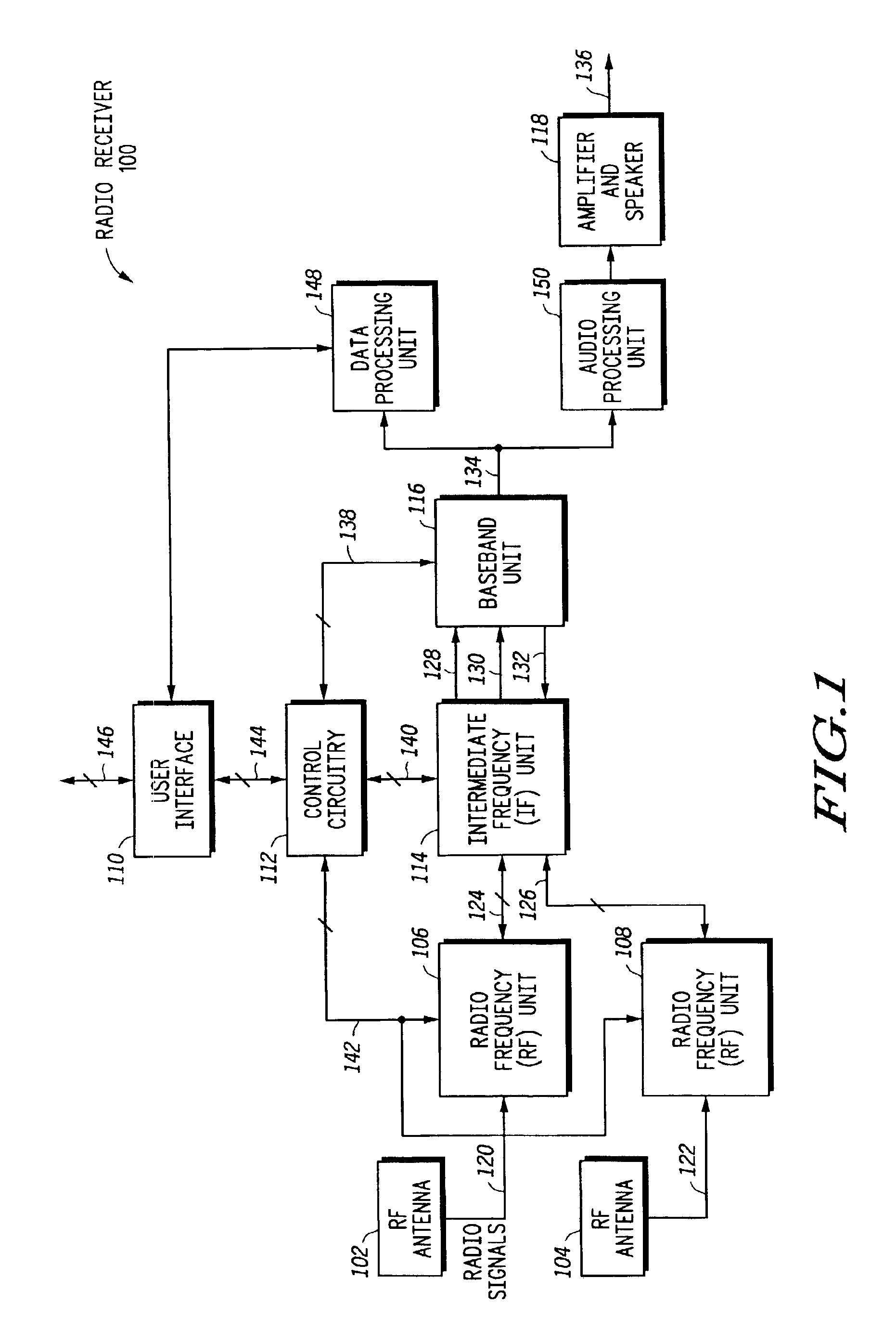
[0014]FIG. 1 illustrates a radio receiver 100 in accordance with one embodiment of the present invention. Radio receiver 100 includes user interface 110 bi-directionally coupled via conductors 144 to control circuitry 112. Control circuitry 112 is coupled to radio frequency (RF) units 106 and 108 via conductors 142, to intermediate frequency (IF) unit 114 via conductors 140, and baseband unit 116 via conductors 138. RF Unit 106 is coupled to RF antenna 102 via conductor 120 and is bi-directionally coupled to IF unit 114 via conductors 124. RF Unit 108 is coupled to RF antenna 104 via conductor 122 and is bi-directionally coupled to IF unit 114 via conductors 126. IF unit 114 is coupled to baseband unit 116 via conductors 128, 130 and 132. Baseband unit 116 is coupled to audio processing unit 150 and data processing unit 148 via conductor 134. Audio processing unit 150 is coupled to amplifier and speaker 118 which provides output signals via conductor 136. Data processing unit 148 is...


PUM


Abstract

A radio receiver (100) has an IF (intermediate frequency) filter (200) for automatically adjusting its intermediate frequency. The filter (200) includes a filter bank (304), an accumulative sub-band formation (322) and an accumulative sub-band power estimator / switch control (324). The filter bank (304) generates sub-bands, each sub-band having a predetermined frequency range. The accumulative sub-band formation (322) selectively sums the sub-bands to provide lowpass filters having incrementally increasing bandwidth. Power estimates of the lowpass filters are used to determine which lowpass filter output is appropriate for adjacent station interference. Also, if there is no adjacent station interference, the IF filter (200) selects the appropriate filter output depending on the signal strength of the desired station.

Description

REFERENCE TO RELATED COPENDING APPLICATIONS[0001]The present application is related to a United States Patent application by Junsung Li et al. having application Ser. No. 09 / 818,337, filed on Mar. 28, 2001, entitled “Radio Receiver Having a Dynamic Bandwidth Filter and Method Therefor” and assigned to the assignee hereof.[0002]The present application is related to a United States Patent Application by Junsung Li et al. having application Ser. No. 10 / 079,352, filed on Feb. 20, 2002, entitled “Radio Receiver Having an Adaptive Equalizer and Method Therefor: and assigned to the assignee hereof.FIELD OF THE INVENTION[0003]The present invention relates generally to radio receivers and more specifically to radio receivers having a variable bandwidth intermediate frequency (IF) filter and method therefor.RELATED ART[0004]In broadband FM (frequency modulation) broadcasting systems, one of the most important features of the system is that the bandwidth of the FM modulated signal (radio signa...

Claims


Application Information

Patent Timeline
Patent Type & Authority Patents(United States)
IPC IPC(8): H04B1/10H04J1/12
CPCH04B1/1036H04B1/10H04B1/16
Inventor LI, JUNSONG
Owner NORTH STAR INNOVATIONS
Why Eureka
Try Eureka