Method and apparatus for extracting non-condensable gases in a cooling system

Active Publication Date: 2005-10-25
RAYTHEON CO
View PDF52 Cites 34 Cited by
  • Summary
  • Abstract
  • Description
  • Claims
  • Application Information

AI Technical Summary

Benefits of technology

[0004]From the foregoing, it may be appreciated that a need has arisen for a method and apparatus for efficiently removing undesired gases from the coolant of a cooling system. One form of the invention involves: circulating through a flow loop a cooling fluid which includes a fluid coolant, the flow loop passing through heat-generating structure disposed in an environment having an ambient pressure; reducing a pressure of the cooling fluid at a selected location along the flow loop to a subambient pressure at which the cooling fluid has a boiling temperature less than a temperature of the heat-g

Problems solved by technology

In contrast, there are other circuits which consume large amounts of power, and produce large amounts of heat.
Existing cooling systems of this type will leak coolant at potential leakage sites, and leakage of coolant may be cause for the system to be shut down.
Although existing units of this type have been generally adequate for their intended purposes, they have not been satisfactory in all respects.
For example, in the case of a subambient cooling system with a two-

Method used


Image

  • Method and apparatus for extracting non-condensable gases in a cooling system
  • Method and apparatus for extracting non-condensable gases in a cooling system

Examples


Example

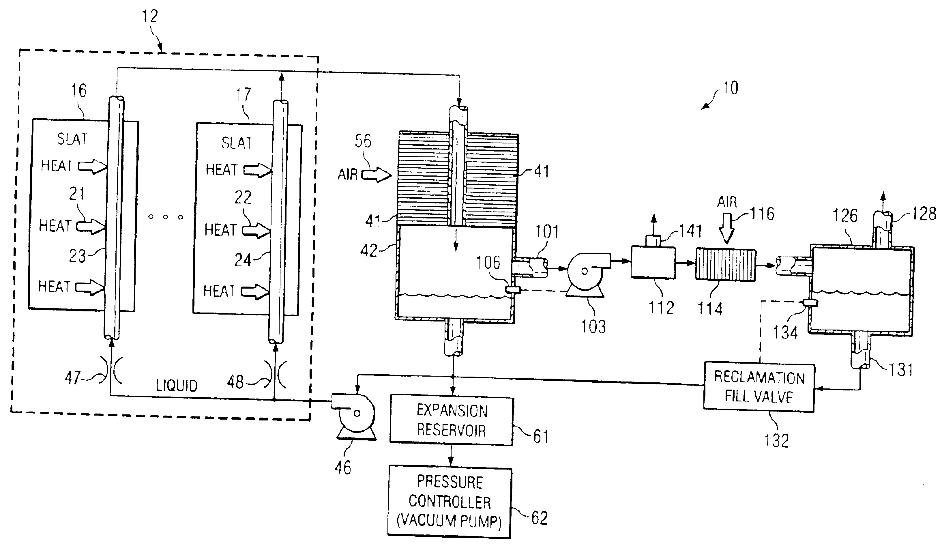
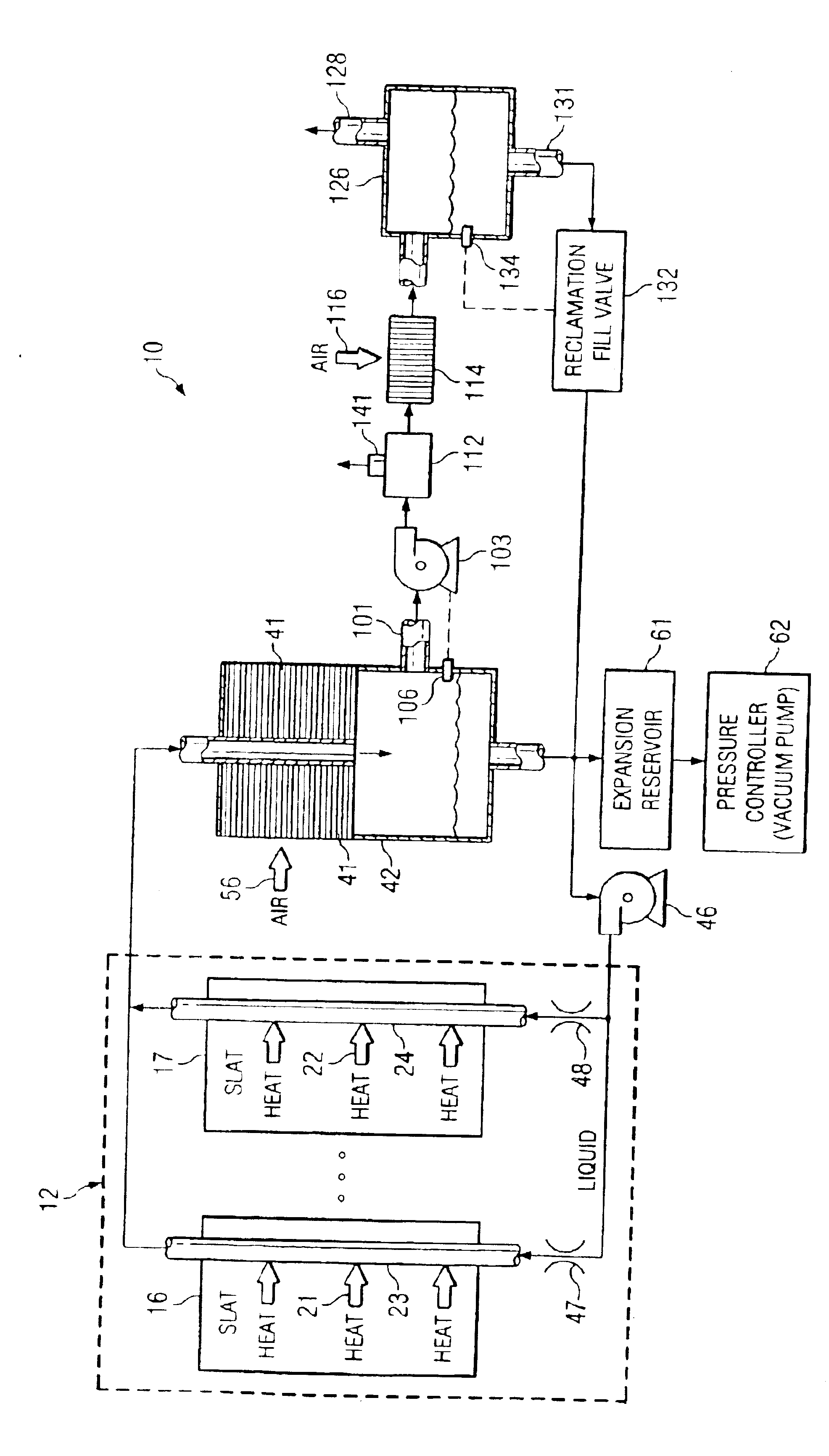
[0006]The drawing is a block diagram of an apparatus 10 which includes a phased array antenna system 12. The antenna system 12 includes a plurality of identical modular parts that are commonly known as slats, two of which are depicted at 16 and 17. A feature of the present invention involves techniques for cooling the slats 16 and 17, so as to remove heat generated by electronic circuitry therein.

[0007]The electronic circuitry within the antenna system 12 has a known configuration, and is therefore not illustrated and described here in detail. Instead, the circuitry is described only briefly here, to an extent which facilitates an understanding of the present invention. In particular, the antenna system 12 includes a two-dimensional array of not-illustrated antenna elements, each column of the antenna elements being provided on a respective one of the slats, including the slats 16 and 17. Each slat includes separate and not-illustrated transmit / receive circuitry for each antenna ele...


PUM


Abstract

A cooling technique involves: reducing a pressure of a cooling fluid to a subambient pressure at which the cooling fluid has a boiling temperature less than a temperature of a heat-generating structure; bringing the cooling fluid at the subambient pressure into thermal communication with the heat-generating structure, so that the coolant absorbs heat, boils and vaporizes; thereafter removing heat from the coolant so as to condense substantially all of the coolant to a liquid; and thereafter extracting a selected portion of the cooling fluid that has been cooled, the selected portion being a vapor that includes a non-condensable gas.

Description

BACKGROUND OF THE INVENTION[0001]Some types of electronic circuits use relatively little power, and produce little heat. Circuits of this type can usually be cooled satisfactorily through a passive approach, such as conduction cooling. In contrast, there are other circuits which consume large amounts of power, and produce large amounts of heat. One example is the circuitry used in a phased array antenna system.[0002]More specifically, a modern phased array antenna system can easily produce 25 to 30 kilowatts of heat, or even more, and thus requires about 25 to 30 kilowatts of cooling. Existing systems for cooling this type of circuitry utilize an active cooling approach, in which a fluid coolant is circulated. Existing cooling systems of this type will leak coolant at potential leakage sites, and leakage of coolant may be cause for the system to be shut down. A more recent approach, which can better handle newer circuitry that produces larger amounts of waste heat, involves a coolin...

Claims


Application Information

Patent Timeline
IPC IPC(8): F25B23/00F28D15/02F25B43/04
CPCF25B23/006F28D15/0266F25B43/04F28F2265/14F28F2265/18
Inventor WYATT, WILLIAM GERALDWEBER, RICHARD M.
Owner RAYTHEON CO
Why Eureka
Try Eureka