Cutting insert with curved cutting edge

Inactive Publication Date: 2005-10-25
KORLOY
View PDF12 Cites 56 Cited by
  • Summary
  • Abstract
  • Description
  • Claims
  • Application Information

AI Technical Summary

Benefits of technology

[0018]According to the above-mentioned present invention, the cutting insert for a milling machining is constructed such that the primary cutting edge has an arcuate edge line becoming convex toward the adjacent secondary cutting edge, and then tangential to the straight shaped adjacent secondary cutting edge as viewed in plan, and is gradually decreased in height toward the secondary cutting edge, and then tangential to the straight shaped adjacent secondary cutting edge as viewed in front elevat

Problems solved by technology

Therefore, the right angularity of the machined side surface, i.e., the right angularity between the side faces and the bottom faces of the machined workpiece, can be partially improved but cannot be perfectly achieved in th

Method used


Image

  • Cutting insert with curved cutting edge
  • Cutting insert with curved cutting edge
  • Cutting insert with curved cutting edge

Examples


Embodiment Construction

[0029]Reference should now be made to the drawings, in which the same reference numerals are used throughout the different drawings to designate the same or similar components.

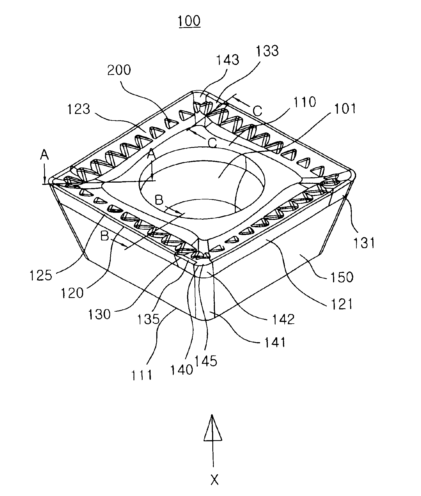
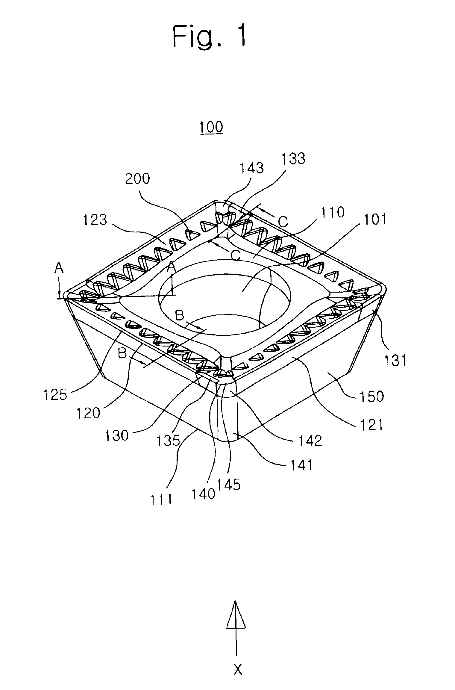
[0030]FIG. 1 is a perspective view showing a cutting insert for a milling machining according to the present invention.

[0031]As shown in the drawing, the cutting insert for milling machining according to the invention is usually made of a cemented carbide material utilizing a powder metallurgy process such as an embossing, a sintering, a grinding, a coating or the like. The cutting insert 100 for milling machining uses only its upper face 110 in the case of a cutting operation of ferrous metal or nonferrous metal. For this purpose, only the upper face 110 is provided with chip breakers 200.

[0032]The cutting insert 100 is formed at its center portion with a circular aperture 101 which is vertically perforated therethough. The cutting insert 100 is shaped to have four sides as viewed in plan. Four corner portion...


PUM

PropertyMeasurementUnit
Angleaaaaaaaaaa
Angleaaaaaaaaaa
Angleaaaaaaaaaa

Abstract

A cutting insert for a milling machining adapted to be mounted on a milling cutter to carry out cutting operation and having primary and secondary cutting edges provided at sides of a rectangular body, each primary cutting edge having a curved line tangential to the adjacent secondary cutting edge, to reduce the cutting force and improve flatness of the side surface of a machined workpiece. The cutting insert includes an upper face, a bottom face and a plurality of side faces connecting the upper face and the bottom face. The primary cutting edge has chip breakers for guiding chip flow, primary cutting edge land faces and primary cutting edge clearance faces. The primary cutting edges enable a bottom surface and a side surface of a machined workpiece to have a right angle therebetween.

Description

[0001]This application is the national phase under 35 U.S.C. §317 of PCT International Application No. PCT / KR01 / 01388 which has an International filing date of Aug. 16, 2001, which designated the United States of America.TECHNICAL FIELD[0002]The present invention relates, in general, to a cutting insert with arcuate cutting edges adapted to be mounted in a milling cutter for cutting a workpiece in a desired shape, and, more particularly, to a cutting insert for a milling machining which has primary cutting edges, each being composed of an arcuate line becoming the most convex at a point meeting an adjacent secondary cutting edge, as viewed in plan and becoming the most concave at a point meeting the adjacent secondary cutting edge as viewed in front elevation, to carry out milling machining such as plane machining, side machining, slot machining, hole machining or the like. Accordingly, the present invention improves the quality of machined surfaces of a workpiece, reduces cutting r...

Claims


Application Information

Patent Timeline
IPC IPC(8): B23C5/20B23C5/16B23C9/00
CPCB23C5/202B23C2200/203B23C2200/283Y10T407/235Y10T407/245Y10T407/23B23C2200/323B23C9/00
Inventor SUNG, WOOK JUNGLEE, KWAN HEELEE, YONG BOOKIM, YOUNG HEUMKIM, HAK KYUKIM, KYUNG BAE
Owner KORLOY
Why Eureka
Try Eureka