Coil bobbin with core spacing mechanisms

a core spacing and coil technology, applied in the field of coil bobbins, can solve the problems of quality problems and hinder the working efficiency, and achieve the effects of preventing the gap from growing, preventing the magnetic reluctance from increasing, and keeping the inductance of the transformer or choke coil constan

Inactive Publication Date: 2005-10-25
MINEBEA CO LTD
View PDF4 Cites 24 Cited by
  • Summary
  • Abstract
  • Description
  • Claims
  • Application Information

AI Technical Summary

Benefits of technology

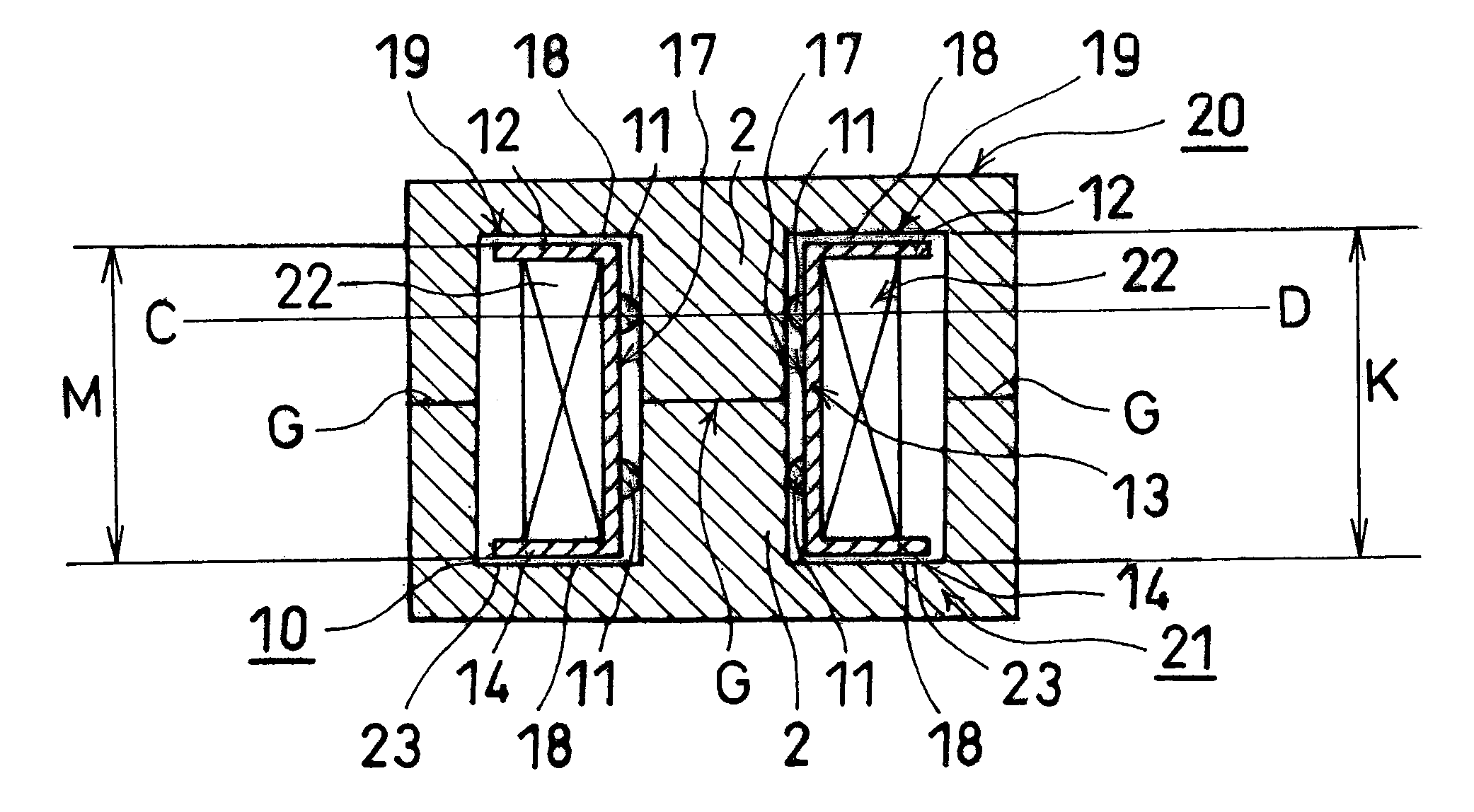
[0016]Consequently, the magnetic core is prevented from getting firmly fixed to the coil bobbin by means of varnish through a varnish impregnation treatment, thus preventing a gap from growing at the abutting contact surface between the two core sections even when the coil bobbin undergoes a dimensional change due to the ambient temperature or humidity change. As a result, magnetic reluctance is prevented from increasing, whereby the inductance of a transformer or choke coil is kept constant.
[0017]Further, the material of a coil bobbin is conventionally selected according to its application such that a thermoplastic resin, which suffers a small dimensional change due to the ambient temperature or humidity change (for example, polybutylene-terephthalate), is used when the coil bobbin is preferred to be environment-resistant, and a thermosetting resin (for example, phenol) is used when the coil bobbin is preferred to be heat-resistant, for example, during soldering process. In the present invention, the coil bobbin formed of a thermosetting resin can be environment-resistant as well as heat-resistant, which eliminates the troublesome selection of the coil bobbin material according to its application, and which ensures heat-resistance preventing the coil bobbin from deforming or terminal pins from bending due to the heat from the soldering work and therefore eliminating special caution during the soldering work improving the work efficiency.

Problems solved by technology

While the varnish impregnation treatment improves insulation performance of the winding section and also stabilities against electrical oscillation and mechanical oscillation, it creates the following problem.
However, the coil bobbin formed of the thermoplastic resin (polybutylene-terephthalate) is easily deformed or its terminal pins are easily bent due to heat applied when the coil is subjected to soldering work, which causes a quality problem.
Further, the soldering work requires a special caution, thereby hindering the working efficiency.

Method used


Image

  • Coil bobbin with core spacing mechanisms
  • Coil bobbin with core spacing mechanisms
  • Coil bobbin with core spacing mechanisms

Examples


Embodiment Construction

[0026]Preferred embodiments of the present invention will hereinafter be described with reference to the accompanying drawings.

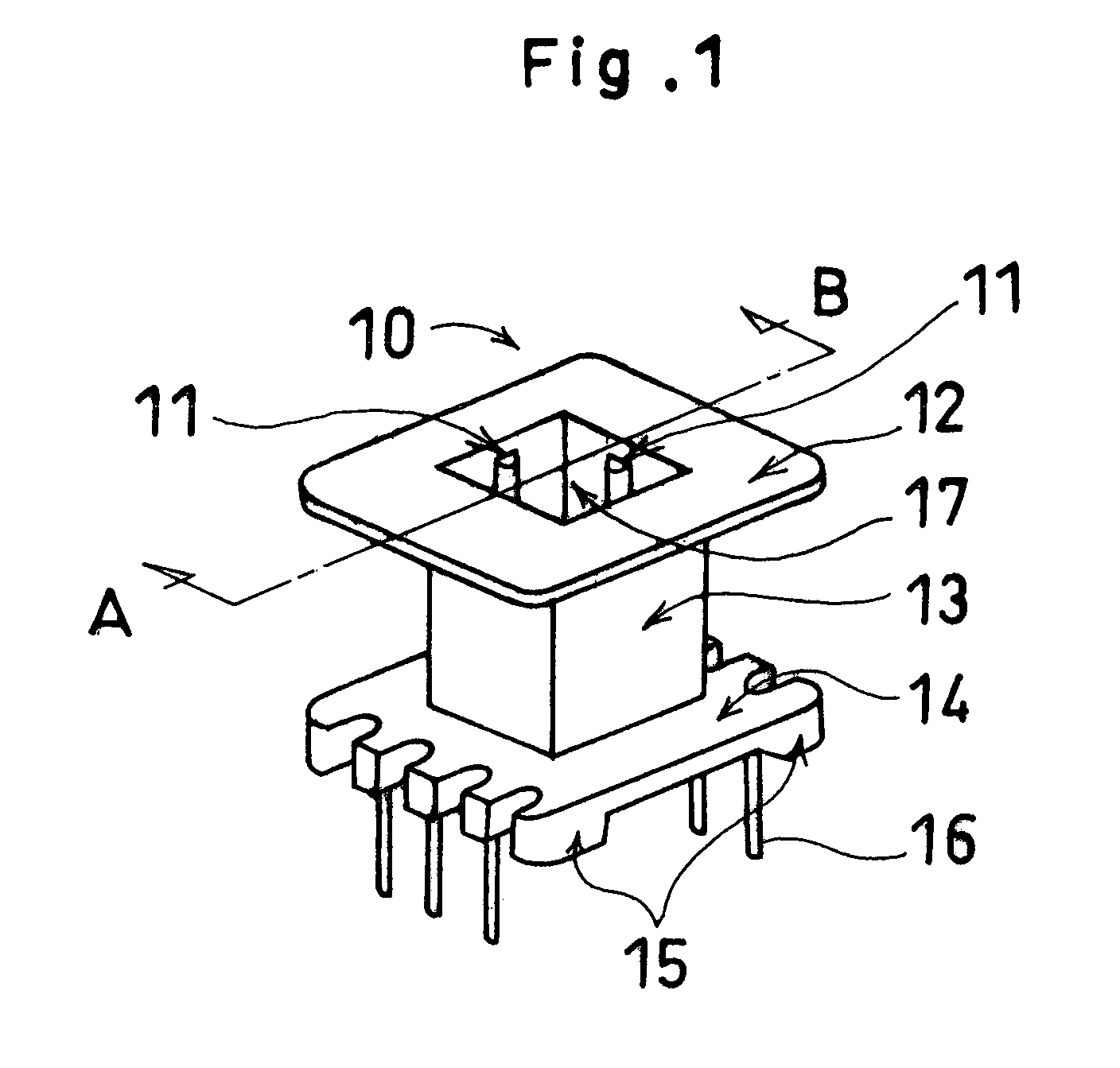
[0027]Referring to FIG. 1, a coil bobbin 10 comprises a top flange 12, a base flange 14, and a core housing portion 13 formed therebetween. The base flange 14 has terminal pins 16 to which a winding (not shown) is connected, and is provided with coil stand portions 15. The core housing portion 13 is of square tubular structure, has a magnet wire (not shown) wound therearound, and has at least one core spacing mechanism 11 provided on each of four surfaces of its inner wall 17 and formed into a linear ridge extending straight in the direction of inserting the magnetic core.

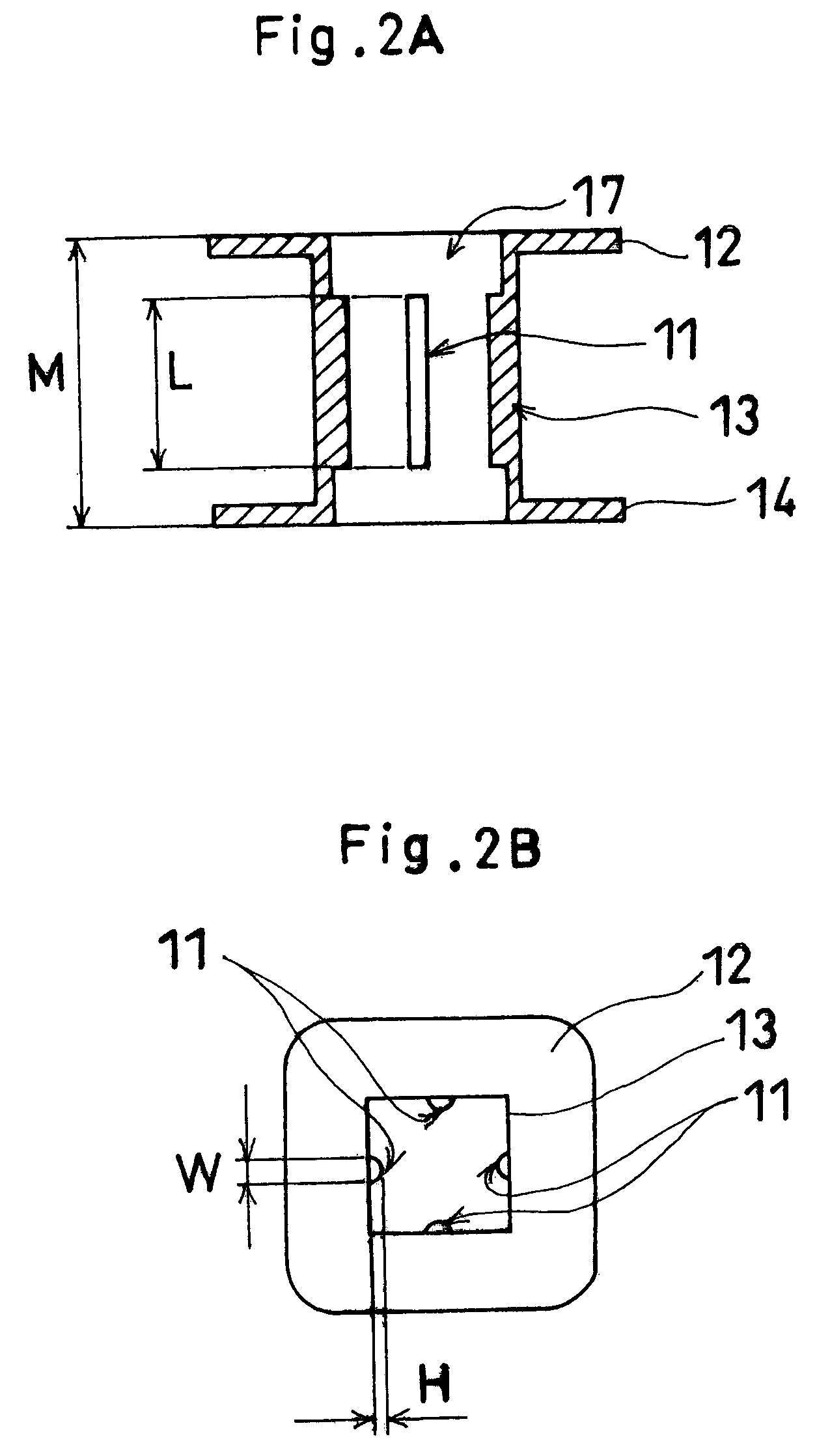
[0028]Referring now to FIGS. 2A and 2B, each of the core spacing mechanisms 11 has a length L smaller than a length M of the core housing portion 13, which is defined by the distance from the outside of the top flange 12 to the outside of the base flange 14. Also, as described later with re...


PUM

PropertyMeasurementUnit
heightaaaaaaaaaa
heightaaaaaaaaaa
magneticaaaaaaaaaa

Abstract

A coil bobbin comprises a core housing portion which has a magnet wire wound therearound, and which undergoes a varnish impregnation treatment together with a magnetic core consisting of two core sections, like an EE type or UU type. Core spacing mechanisms are formed on the inner surfaces of the core housing portion, and control a position of the magnetic core inserted in the core housing portion such that the magnetic core is kept apart from the inner surfaces of the core housing portion.

Description

BACKGROUND OF THE INVENTION[0001]1. Field of the Invention[0002]The present invention relates to a coil bobbin, and particularly to a coil bobbin which undergoes a varnish impregnation treatment together with a magnetic core.[0003]2. Description of the Related Art[0004]A conventional transformer or choke coil comprises a magnetic core using a ferrite core and a plastic bobbin having a magnet wire wound therearound. The magnetic core consists of two separate sections like EE type, or UU type, where the two separate core sections abut against each other to form a closed magnetic path. In the structure, a gap may grow at the abutting contact portion and acts as a critical factor determining magnetic characteristics of the core. The abutting contact condition may be secured by adhesively bonding, taping or by means of a metallic spring.[0005]The transformer or choke coil may undergo a well-known varnish impregnation treatment together with its magnetic core depending on its application....

Claims


Application Information

Patent Timeline
Patent Type & Authority Patents(United States)
IPC IPC(8): H01F27/32H01F27/26H01F27/02H01F5/02
CPCH01F27/022H01F27/263H01F27/325
Inventor SUZUKI, MITSUAKI
Owner MINEBEA CO LTD
Why Eureka
Try Eureka