Small-sized and high-gained antenna-integrated module

a technology of integrated modules and antennas, applied in the direction of antenna couplings, resonant antennas, antenna equipments with additional functions, etc., can solve the problems of increasing the number of parts and manufacturing costs of the modules, difficult to reduce the size of the modules, and difficult to achieve an antenna-integrated module with a high gain. , to achieve the effect of easy secure the wide area of the electrod

Active Publication Date: 2005-10-25
ALPS ALPINE CO LTD
View PDF7 Cites 27 Cited by
  • Summary
  • Abstract
  • Description
  • Claims
  • Application Information

AI Technical Summary

Benefits of technology

[0008]Accordingly, the present invention is designed to solve the above problems, and it is an object of the present invention to provide an antenna-integrated module having a small size, a high gain, and low manufacturing costs.
[0010]In the antenna-integrated module in which a conductor portion of the cover that covers the main parts of the high frequency circuit and is connected to the ground functions as an antenna element, since the conductor portion of the cover can almost shield the high frequency circuit from an electromagnetic field, it is not necessary to provide both the antenna element and the shield case on the circuit board. That is, in the antenna-integrated module of the present invention, since the antenna element also functions as the shield case, it is possible to remarkably decrease the entire size of the module and thus to decrease the number of parts thereof, thereby reducing manufacturing costs thereof. In addition, since an antenna element having almost the same size as the circuit board can be used, it is possible to achieve an antenna-integrated module having a high gain.
[0013]Moreover, when the ground pattern of the high frequency circuit is formed on the lower surface or in an inner layer (in the case of a multi-layered board) of the circuit board, it is possible to use the ground pattern as another electrode of the antenna, and thus to easily secure the wide area of the electrode.

Problems solved by technology

Thus, it is difficult to decrease the size of the module.
In addition, in the conventional antenna-integrated module, since the antenna element must be provided in limited space on the circuit board, the size of the antenna element itself is strictly restricted, and thus it is difficult to achieve an antenna-integrated module having a high gain.
As a result, the number of parts and manufacturing costs of the module are increased.

Method used


Image

  • Small-sized and high-gained antenna-integrated module
  • Small-sized and high-gained antenna-integrated module
  • Small-sized and high-gained antenna-integrated module

Examples


first embodiment

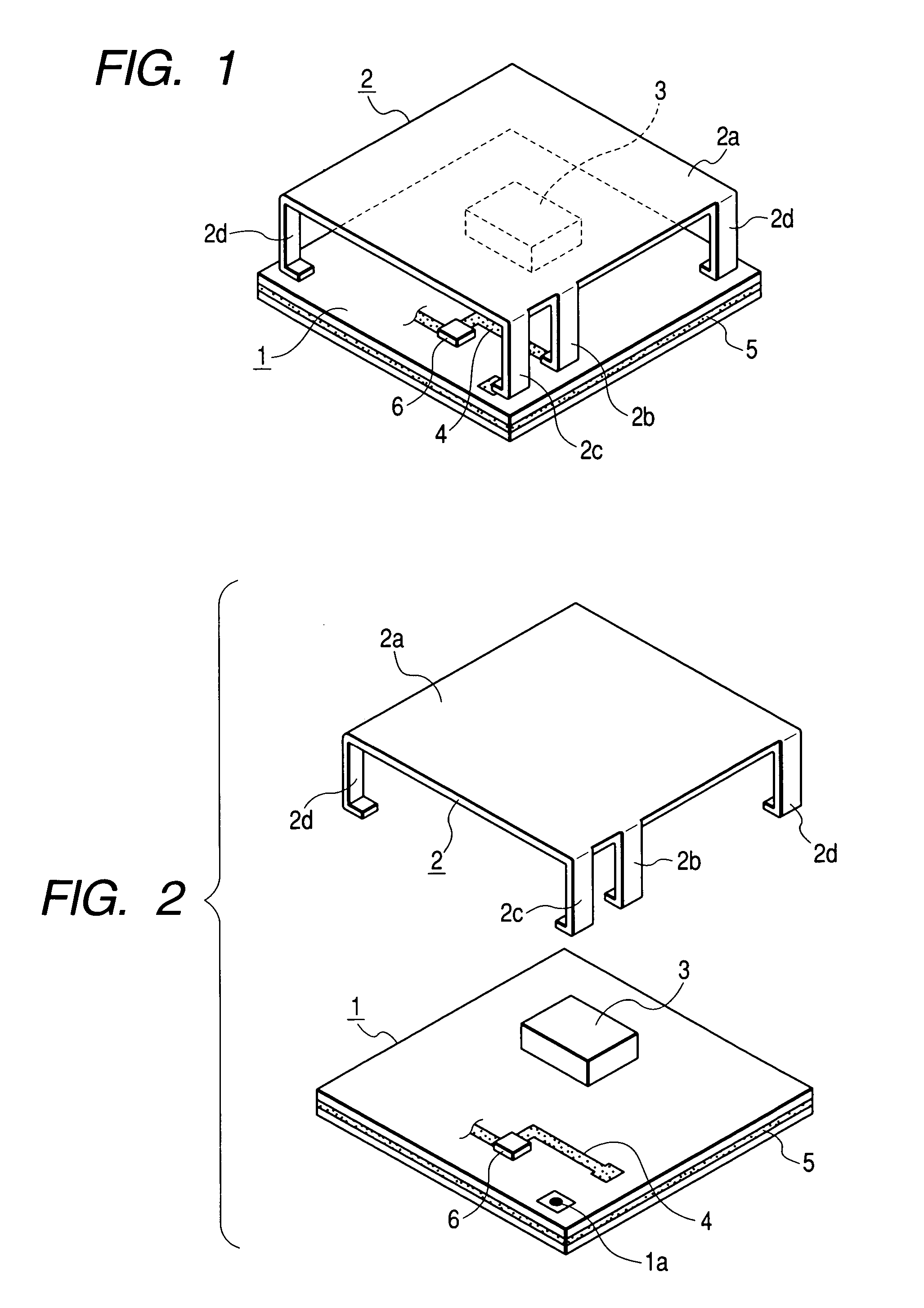
[0018]Hereinafter, embodiments of the present invention will be described with reference to the accompanying drawings. FIG. 1 is a perspective view of an antenna-integrated module according to the present invention, and FIG. 2 is an exploded perspective view of the antenna-integrated module.

[0019]The antenna-integrated module shown in the drawings comprises a circuit board 1 on which a high frequency circuit is arranged, a cover 2 that is composed of a metal plate and is mounted to the circuit board 1 so as to cover almost the entire surface thereof, and a dedicated shield case 3 that is composed of a metal plate and is mounted to the circuit board 1 so as to cover a specific region thereon. The high frequency circuit of the module comprises a wiring pattern 4 formed on the upper surface and lower surface of the circuit board 1, which is a multi-layered board, a ground pattern 5 formed on an inner layer of the circuit board 1, and various electronic parts 6, such as chip parts and I...

second embodiment

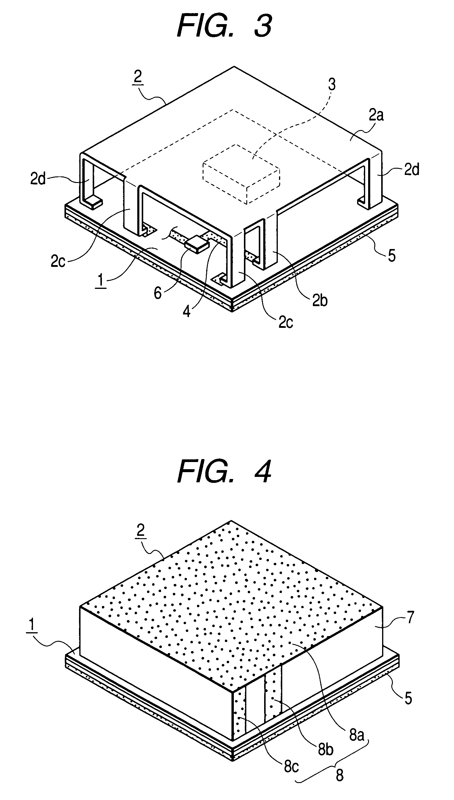
[0023]FIG. 3 is a perspective view of an antenna-integrated module according to the present invention. In FIG. 3, the same components as those in FIGS. 1 and 2 have the same reference numerals.

[0024]The second embodiment is largely different from the first embodiment in that two leg pieces 2c functioning as ground conductor portions are provided on the cover 2, and the distance from one leg piece 2c to the leg piece 2b functioning as the feeding conductor portion is different from the distance from the other leg piece 2c to the leg piece 2b. As a result, it is possible to make the cover 2 function as an antenna element having a wider bandwidth than that of a conventional inverted F-type antenna. In addition, according to the present embodiment, the ground pattern 5 is formed on the lower surface of the circuit board 1.

third embodiment

[0025]FIG. 4 is a perspective view of an antenna-integrated module according to the present invention. In FIG. 4, the same components as those in FIGS. 1 to 3 have the same reference numerals.

[0026]The third embodiment is greatly different from the first and second embodiments in that the cover 2 is not composed of a metal plate but is formed by providing a conductive layer 8 on the surface of a box-shaped case 7 made of synthetic resin, an upper plate coating portion 8a of the conductive layer 8 that is provided over the entire surface of an upper plate portion of the box-shaped case 7 functions as the radiation conductor portion, and a pair of strip-shaped portions 8b and 8c that is provided on a side wall of the box-shaped case 7 functions as the feeding conductor portion and the ground conductor portion, respectively. In addition, similar to the second embodiment, the ground pattern 5 is formed on the lower surface of the circuit board 1 in the present embodiment.

[0027]According...


PUM


Abstract

The antenna-integrated module contains a circuit board 1 on which a high frequency circuit is provided, a cover 2 that is composed of a metal plate and is mounted to the circuit board 1 so as to cover almost the entire surface of the circuit board 1, and a dedicated shield case 3 that is composed of a metal plate and is mounted to the circuit board 1 so as to cover a specific region on the circuit board 1. The high frequency circuit comprises a wiring pattern 4 and a ground pattern 5, and electronic parts 6, and the dedicated shield case 3 covers a portion of the high frequency circuit. Leg pieces 2b and 2c of the cover 2 are connected to the wiring pattern 4 and the ground pattern 5. In the cover 2, an upper plate 2a corresponding to a radiation conductor portion functions as both an inverted F-type antenna and a shield case.

Description

[0001]This application claims the benefit of priority to Japanese Patent Application No. 2003-165180, herein incorporated by reference.BACKGROUND OF THE INVENTION[0002]1. Field of the Invention[0003]The present invention relates to an antenna-integrated module suitable for a small-sized transmitter-receiver used for communication and broadcasting.[0004]2. Description of the Related Art[0005]In recent years, accompanying with the development of wireless communication techniques, various electronic apparatuses or wireless cards in which small-sized transmitter-receiver units are mounted have been proposed. This kind of transmitter-receiver unit is an antenna-integrated high frequency module in which an antenna element is mounted on a circuit board with a high frequency circuit. In the conventional antenna-integrated module, in general, a shield case composed of a metal plate covers a specific region of the circuit board on which the main parts of the high frequency circuit are arrange...

Claims


Application Information

Patent Timeline
Patent Type & Authority Patents(United States)
IPC IPC(8): H01Q1/00H01Q1/52H01Q9/04H01Q1/24H01Q23/00H01Q13/08
CPCH01Q1/243H01Q1/526H01Q9/0421H01Q1/44
Inventor YUANZHU, DOU
Owner ALPS ALPINE CO LTD
Why Eureka
Try Eureka