Pointing angle control of electrostatic micro mirrors with modified sliding mode control algorithm for precision control

a micro-mirror and sliding mode technology, applied in the field of micro-electromechanical devices, can solve the problems of affecting the overall performance of the device, requiring additional connections between the substrate and the control system, and temperature sensitive piezoresistive angle sensors, etc., to achieve the effect of reducing steady state output error, reducing output noise, and improving setpoint tracking performan

Inactive Publication Date: 2005-10-25
CORNING INC
View PDF19 Cites 18 Cited by
  • Summary
  • Abstract
  • Description
  • Claims
  • Application Information

AI Technical Summary

Benefits of technology

[0018]In other aspects to this, and other, embodiments, the detection mode of the MEMS device may be independent of the detection mode of the frame so that interference between the electrodes is minimized. Additionally, an ASIC may be connected to the electrodes to control the detection and drive modes for the mirror and frame.
[0022]In one aspect of the present invention, a modified sliding mode control algorithm that involves “intelligent” of the differential gain within a band around a desired set point. This modification yields lower output noise and reduced steady state output error along with improved setpoint tracking performance. Additionally, the modified sliding mode control requires minimal implementation space or computational power.

Problems solved by technology

If the pointing angle stability is not sufficient, significant losses, such as port-to-port losses, can occur and the overall performance may be compromised.
One drawback to the use of piezoresistive angle sensors are temperature sensitive and require additional connections between the substrate and the control system.
Additionally, a device that includes piezoresistive angle sensors may be more complicated and more difficult to manufacturing.
Further, each of the above mentioned control systems add to the level of complexity and cost of a MEMS device.
The control systems also occupy space and require additional connections between the MEMS device and the control system.
Changes in the characteristics of the apparatus or disturbance forces acting on it will alter the dynamic response of the system and has limited the application of VSC systems.
A lower differential gain can result in the over shooting the desired set point or even instability.
A very high differential gain results in an over-damped slow tracking response.
However the derivative term is a major source of output noise and tracking error.
The accurate and predictable control of MEMS devices has been elusive.

Method used


Image

  • Pointing angle control of electrostatic micro mirrors with modified sliding mode control algorithm for precision control
  • Pointing angle control of electrostatic micro mirrors with modified sliding mode control algorithm for precision control
  • Pointing angle control of electrostatic micro mirrors with modified sliding mode control algorithm for precision control

Examples


Embodiment Construction

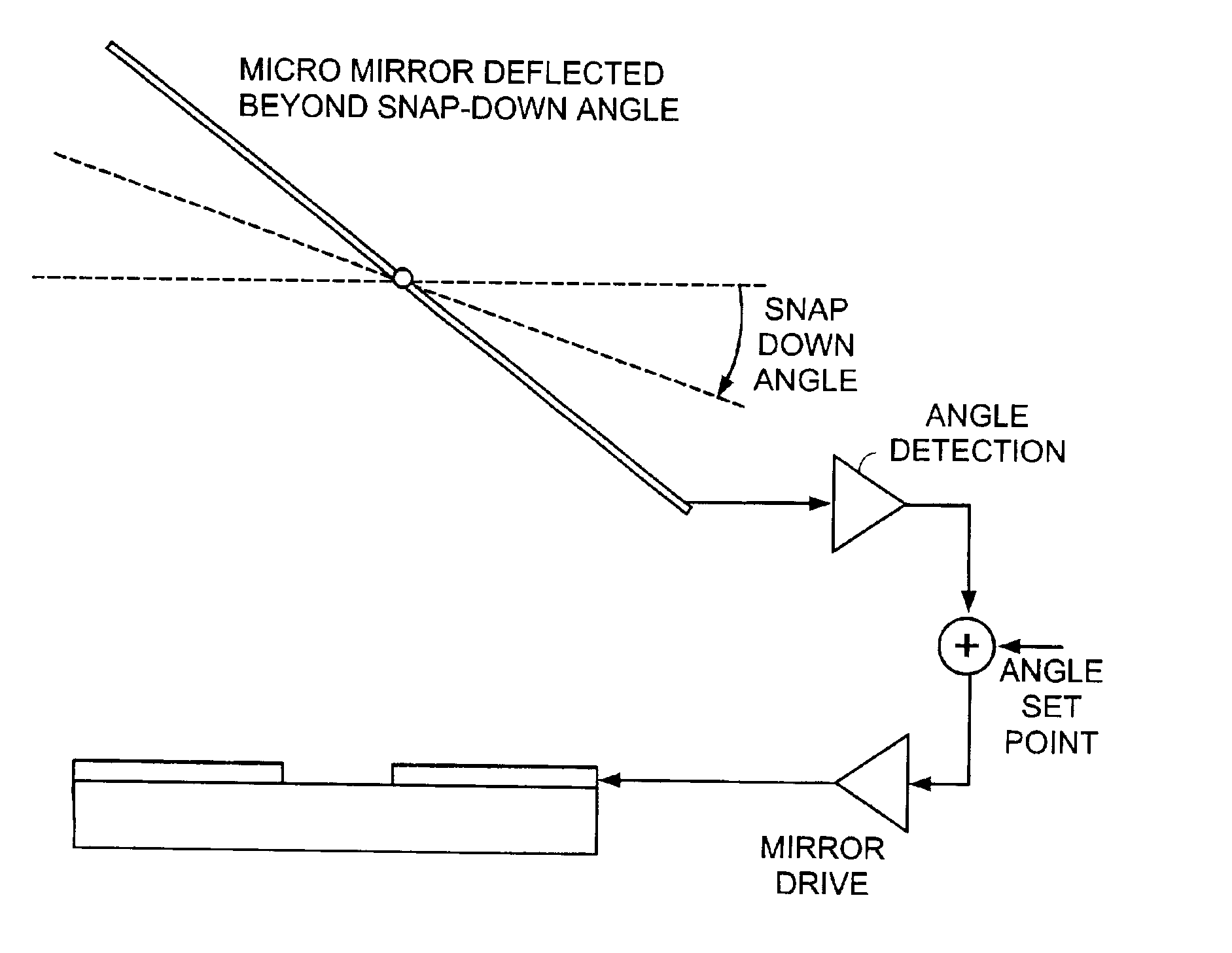
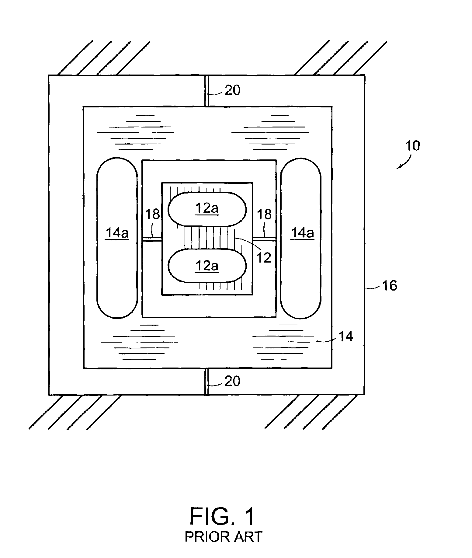
[0036]The present invention provides capacitors for position detection of a MEMS micro mirror and uses a control system, such as sliding mode control, which provides a fast non linear feedback loop to control the position of the mirror. Throughout the specification the MEMS device is referred to as a micro mirror. While this is one suitable application of the technology, one skilled in the art will recognize that the invention can be used in other MEMS devices.

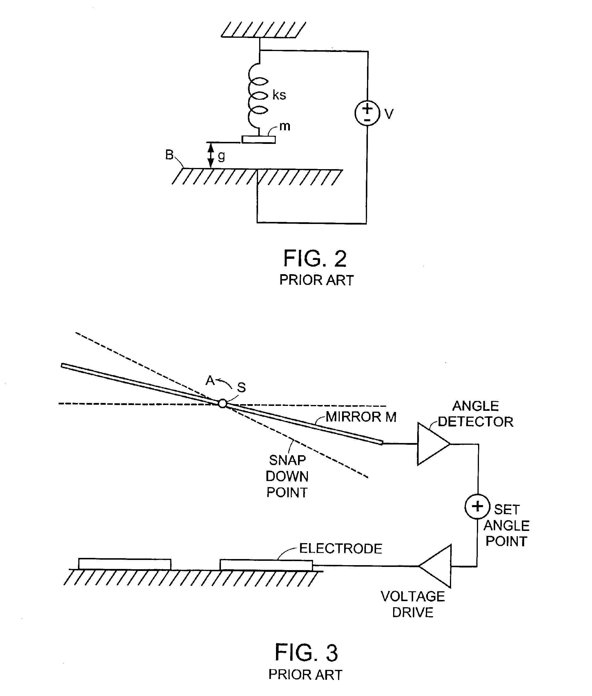
[0037]The specification is divided into three parts. First, the term “snap down point” is introduced as a description of a design parameter that is important in MEMS devices. In the context of the MEMS mirrors, the snap down point limits the deflection of the mirror. Second, the use of closed loop feedback control in MEMS mirrors is discussed. Third, the use of capacitors for position detection is discussed in the context of micro mirrors. Finally, the non linear control feedback loop is introduced by the use of sliding mode c...


PUM

PropertyMeasurementUnit
capacitanceaaaaaaaaaa

Abstract

The present invention is directed to a control system for a MEMS device, such as a MEMS mirror, that uses sliding mode analysis to accurately and predictably control the position of the mirrors in a MEMS device. The present invention also uses the capacitance of the mirror to detect the position of the mirror. In one embodiment, a MEMS mirror device mounted on a substrate is described that includes, a micro mirror that is pivotable about an axis, a first conductive layer on the mirror, a second conductive layer on the substrate, the first and second conductive layers form a first capacitor for determining the position of the mirror. The sliding mode control can be implemented using various drive mechanisms, including electrostatic drives. When used with electrostatic drives, conductive layers that create the capacitors can also be used to drive the mirror. The detection-drive system can be time multiplexed to simplify implementation and to avoid cross talk. An application Specific Integrated Circuit (ASIC) can be used to control the detection and drive of the mirrors.

Description

RELATED APPLICATION[0001]This application is related to earlier filed application U.S. patent application Ser. No. 10 / 096,457, filed Mar. 13, 2002, the entire contents of which is incorporated by reference into this application.BACKGROUND OF THE INVENTION[0002]1. Field of the Invention[0003]The present invention relates generally to micro-electromechanical (MEMS) devices and in particular to MEMS micro mirrors and a method for controlling the angle of deflection of a micro mirror.[0004]2. Description of Related Art[0005]FIG. 1 illustrates a mirror-in-frame design of a mirror pixel device 10. The device incorporates a mirror 12 which is supported by a frame 14 that forms gimbal structure 16. The device includes a pair of pivots 18, 20, one each for enabling movement in each axis of rotation. The pivots may include torsional springs that provide a restoring force for the mirror plate in a desired position. The position of the mirror is determined by the angle of the mirror within the ...

Claims


Application Information

Patent Timeline
Patent Type & Authority Patents(United States)
IPC IPC(8): G02B26/08
CPCG02B26/0841
Inventor SANE, HARSHAD SHRIKRISHNAYAZDI, NAVIDMASTRANGELO, CARLOS HORACIO
Owner CORNING INC
Why Eureka
Try Eureka