Perpendicular magnetic recording head having main magnetic pole layer formed on high-flatness surface, and method of manufacturing the head
- Summary
- Abstract
- Description
- Claims
- Application Information
AI Technical Summary
Benefits of technology
Problems solved by technology
Method used
Image
Examples
first embodiment
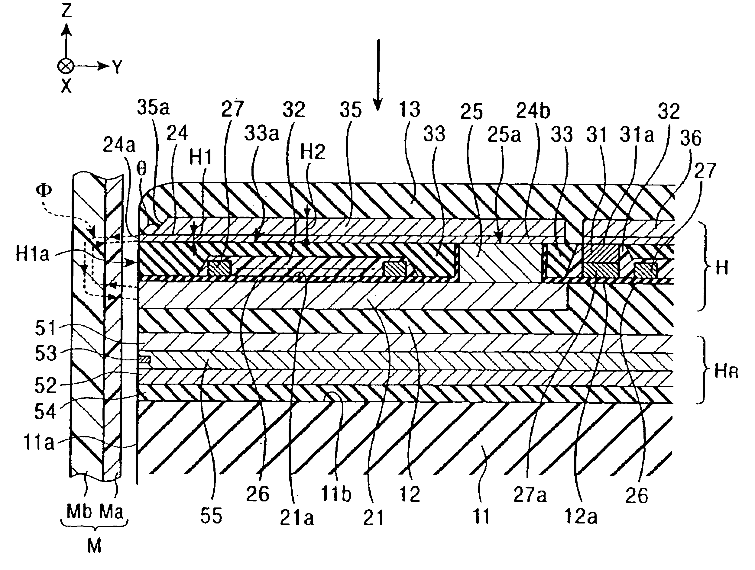
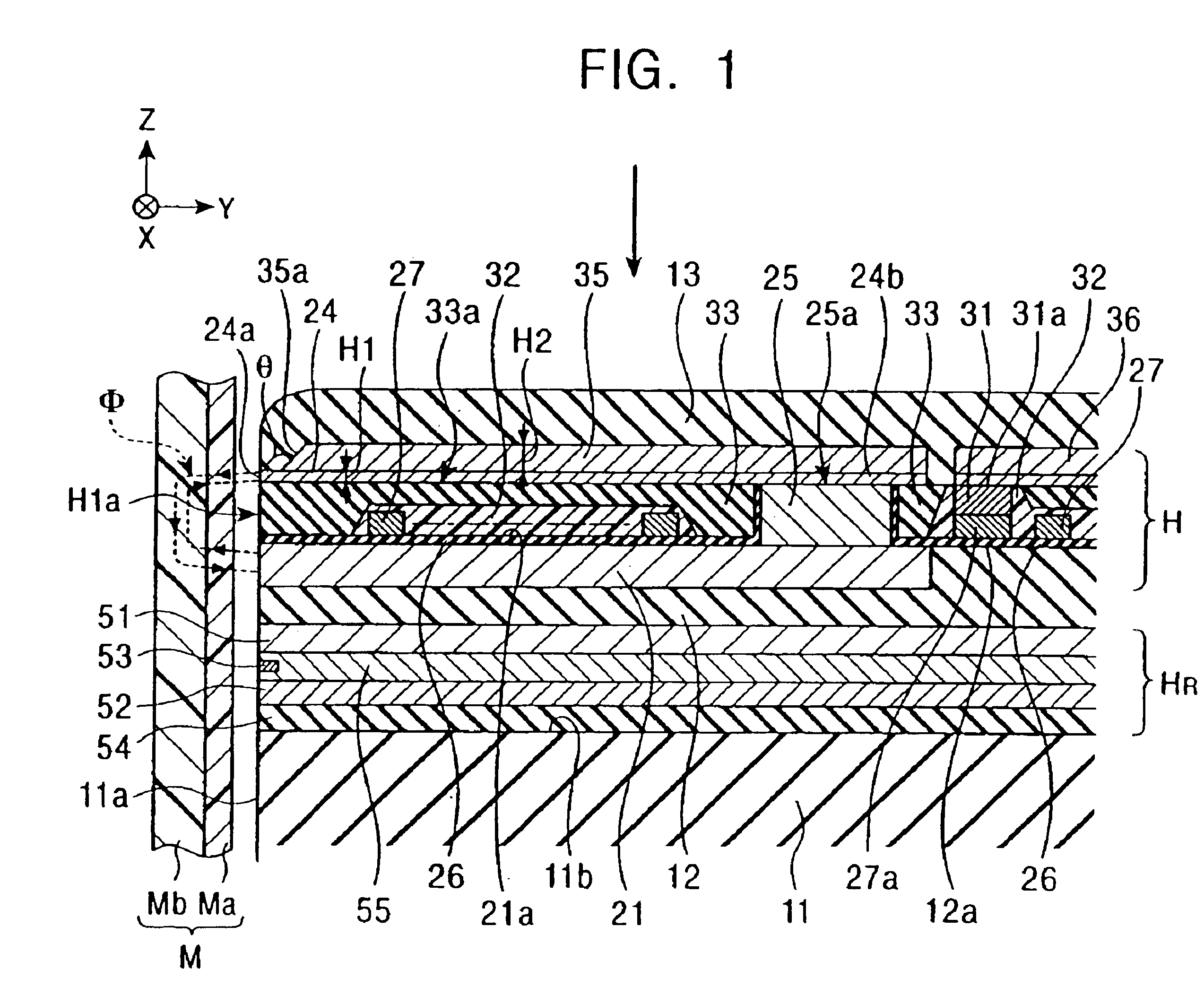
[0084]FIG. 1 is a vertical sectional view showing a structure of a perpendicular magnetic recording head according to the present invention.
[0085]In a perpendicular magnetic recording head H shown in FIG. 1, a perpendicular magnetic field is applied to a recording medium M for magnetizing a hard surface Ma of the recording medium M in the perpendicular direction.
[0086]The recording medium M is in the form of a disk, and has the hard surface Ma on its outer surface, which has high residual magnetization (remanence), and a high soft surface Mb on the inner side, which has a high magnetic permeability. The recording medium M is rotated with the disk center being the center of the rotation.
[0087]A slider 11 of the perpendicular magnetic recording head H is made of ceramic materials, such as Al2O3.TiC. The slider 11 has an opposing surface 11a positioned opposite to the recording medium M. When the recording medium M is rotated, the slider 11 floats from the surface of the recording medi...
second embodiment
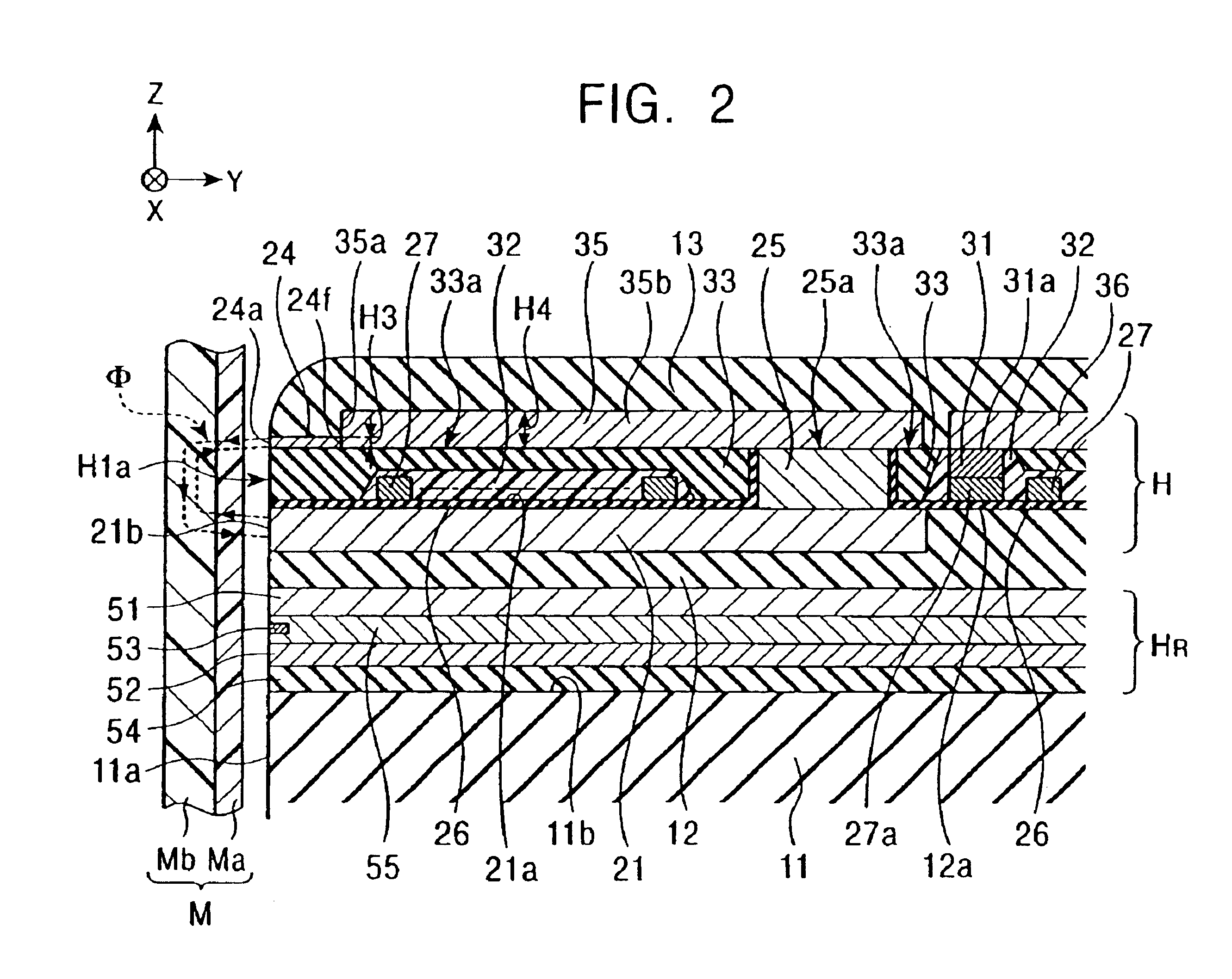
[0111]FIG. 2 is a vertical sectional view showing a structure of a perpendicular magnetic recording head according to the present invention.
[0112]The perpendicular magnetic recording head of FIG. 2 differs from that of FIG. 1 in structure of the main magnetic pole layer 24 and the yoke layer 35, although the yoke layer 35 is formed to have a film thickness H4 larger than a film thickness H3 of the main magnetic pole layer 24 as with the first embodiment. The main magnetic pole layer 24 is formed in a short length to extend from the opposing surface H1a in the height direction (Y-direction in FIG. 2). The yoke layer 35 has a front end surface 35a magnetically coupled to a rear end surface 24f of the main magnetic pole layer 24, and is formed on the insulating layer 33 to extend from the front end surface 35a rearward in the height direction. The yoke layer 35 has a base end portion 35b formed on the upper surface 25a of the connecting layer 25 for magnetic coupling between them.
[0113...
third embodiment
[0116]FIG. 3 is a vertical sectional view showing a structure of a perpendicular magnetic recording head according to the present invention.
[0117]The perpendicular magnetic recording head of FIG. 3 differs from that of FIG. 1 in structure of the main magnetic pole layer 24 and the yoke layer 35, although the yoke layer 35 is formed to have a film thickness H6 larger than a film thickness H5 of the main magnetic pole layer 24 as with the first embodiment. The yoke layer 35 is formed on the insulating layer 33 and has a base end portion 35b magnetically coupled to the upper surface 25a of the connecting layer 25.
[0118]Also, the yoke layer 35 has a front end surface 35a formed as a sloped or curved surface inclined toward the opposing surface H1a as it approaches an upper surface from a lower surface of the yoke layer 35. An external angle θ formed between a lower surface of the main magnetic pole layer 24, which is formed on the yoke layer 35, and the front end surface 35a of the yoke...
PUM
| Property | Measurement | Unit |
|---|---|---|
| Width | aaaaa | aaaaa |
| Height | aaaaa | aaaaa |
Abstract
Description
Claims
Application Information
 - R&D
- Intellectual Property
- Life Sciences
- Materials
- Tech Scout
- Unparalleled Data Quality
- Higher Quality Content
- 60% Fewer Hallucinations
Browse by: Latest US Patents, China's latest patents, Technical Efficacy Thesaurus, Application Domain, Technology Topic, Popular Technical Reports.
© 2025 PatSnap. All rights reserved.Legal|Privacy policy|Modern Slavery Act Transparency Statement|Sitemap|About US| Contact US: help@patsnap.com


