
Method of enhancing signal tracking in global positioning system receivers

a global positioning system and receiver technology, applied in the direction of instruments, navigation instruments, amplitude demodulation, etc., can solve the problems of receivers losing the ability to track carriers, receivers losing the ability to acquire signals, and frequency bins on the extremes of patterns being non-useful, etc., to achieve the effect of enhancing signal tracking

Active Publication Date: 2005-10-25
ROCKWELL COLLINS INC
View PDF4 Cites 38 Cited by
  • Summary
  • Abstract
  • Description
  • Claims
  • Application Information

AI Technical Summary

Benefits of technology

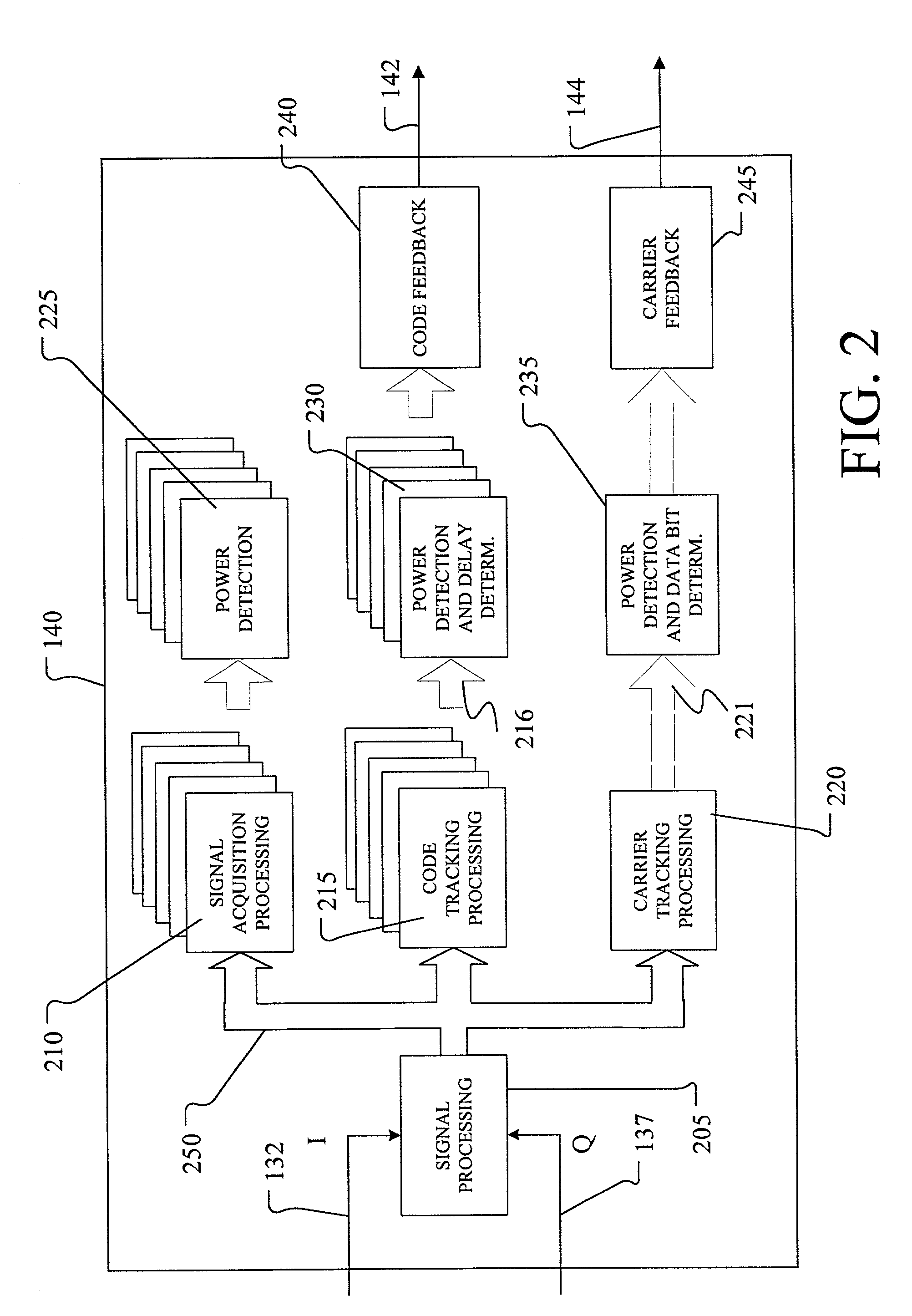
[0009]A method of enhancing signal tracking in a global positioning system receiver utilizing a frequency banked filter in providing code and carrier tracking loops includes acquiring a continuous time global positioning signal and separating the continuous time global positioning signal into in-phase and quadrature signals I and Q. The signals I and Q are sampled over a predetection interval (PDI) to provide discrete time signals, and the discrete time signals are used to generate a component in-phase measurement and a component quadrature measurement for each of multiple PDI segments of one PDI. F

Problems solved by technology

If the frequency error is large, acquisition of the signal is more difficult because of the effective bandwidth of the coherent integration process.
Further still, utilization of an FFT typically produces frequency bins with frequencies up to plus and minus one-half the interval between samples, thereby causing the frequency bins on the extremes of the pattern to be non-useful because of the attenuation caused by integration over the segment.
However, as the signal begins to degrade, the receiver can lose the ability to track the carrier, and the receiver enters a mode of operation known as “State 3” operation.

Method used


Image

  • Method of enhancing signal tracking in global positioning system receivers
  • Method of enhancing signal tracking in global positioning system receivers
  • Method of enhancing signal tracking in global positioning system receivers

Examples


Embodiment Construction

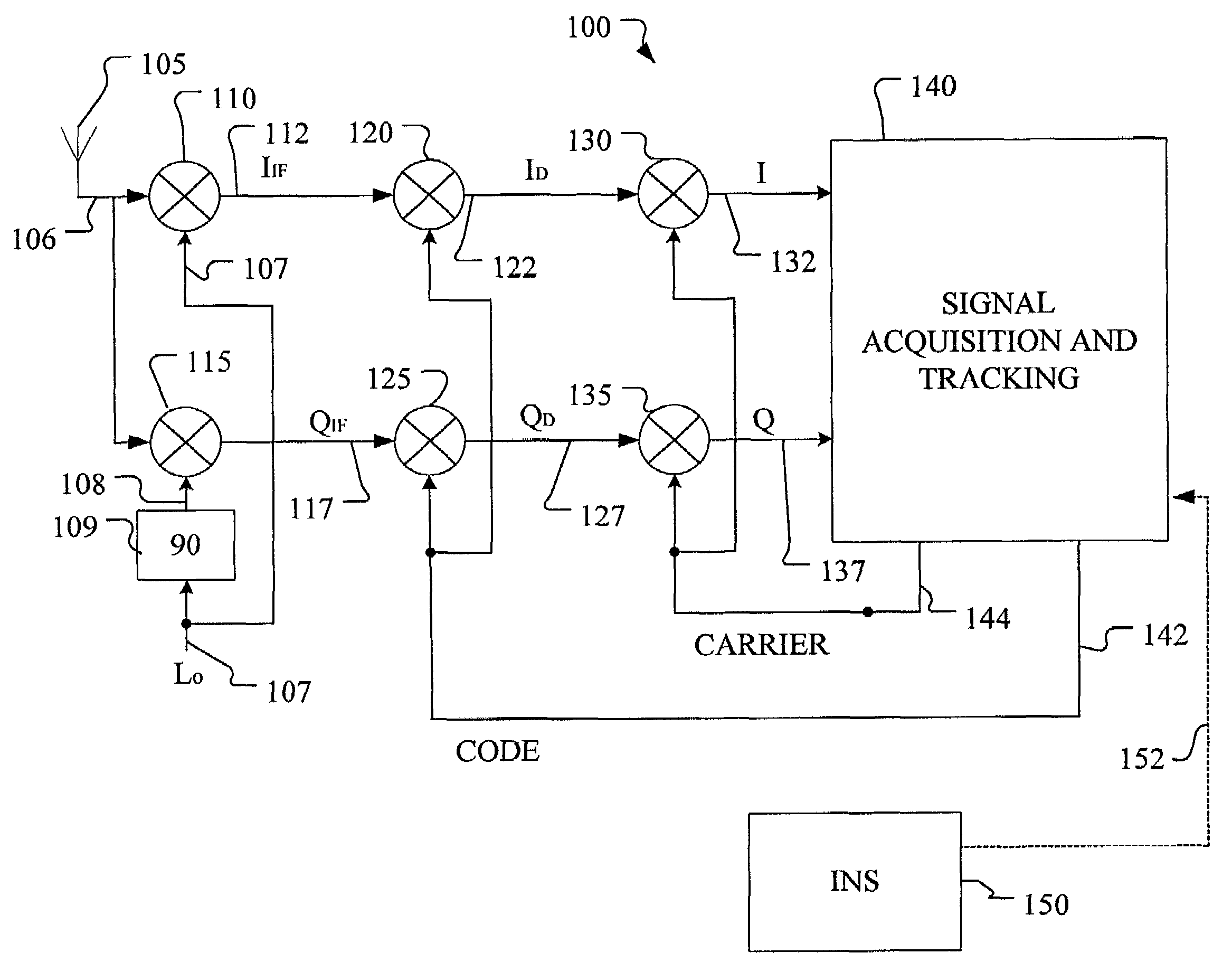
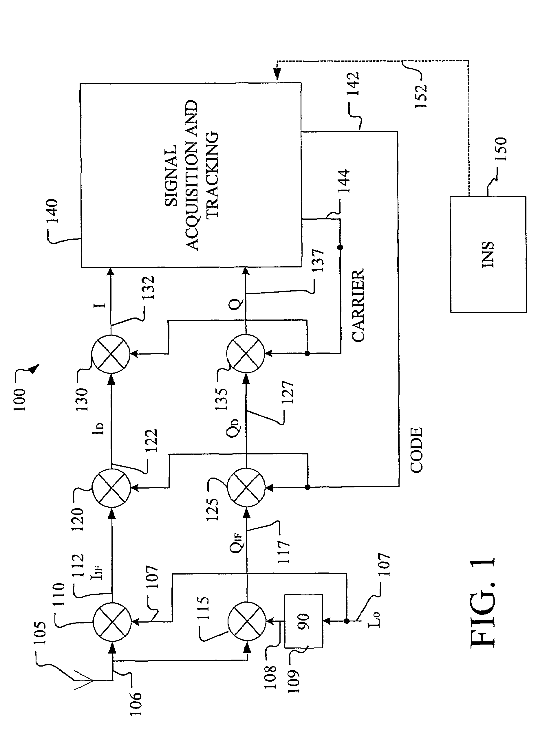
[0019]FIG. 1 is a diagrammatic illustration of portions of GPS receiver 100 in accordance with embodiments of the present invention. FIG. 1 illustrates both general and conventional signal processing stages implemented in conventional GPS receivers, and signal tracking functions implemented in accordance with the present invention. The illustration of both the conventional signal processing stages and of the signal tracking stage is diagrammatic and is not intended to limit the invention to a particular embodiment. For example, the signal frequency down-conversion, code de-spreading, and carrier de-spreading stages illustrated in FIG. 1 can be implemented in a different order or can be combined into fewer stages. Further, aspects of the invention illustrated in functional steps or stages are representative of the corresponding circuitry, including suitably programmed processors or other controllers or components. Thus, the following discussion is intended to teach the concepts of th...


PUM


Abstract

A method of enhancing signal tracking in a global positioning system receiver utilizing a frequency banked filter in providing code and carrier tracking loops includes acquiring a continuous time global positioning signal and separating the continuous time global positioning signal into in-phase and quadrature signals I and Q. The signals I and Q are sampled over a predetection interval (PDI) to provide discrete time signals, and the discrete time signals are used to generate a component in-phase measurement and a component quadrature measurement for each of multiple PDI segments of one PDI. For each of multiple different frequency bins, composite in-phase and quadrature measurements are generated by combining component in-phase measurements and component quadrature measurements from the PDI. Power is detected in each of the multiple different frequency bins for the PDI using the corresponding composite in-phase measurement and the corresponding composite quadrature measurement generated for the frequency bin.

Description

CROSS-REFERENCE TO RELATED APPLICATIONS[0001]Reference is made to co-pending and commonly assigned patent application Ser. No. 08 / 963,930, filed on Nov. 4, 1998, and entitled “MULTIPLE FREQUENCY BIN PROCESSING”, which is herein incorporated by reference in it entirety.FIELD OF THE INVENTION[0002]The present invention relates generally to global positioning system (GPS) receivers. More particularly, the present invention relates to methods for enhancing signal tracking in GPS receivers.BACKGROUND OF THE INVENTION[0003]Global navigational satellite systems (GNSS) are known and include the global positioning system (GPS) and the Russian global orbiting navigational satellite system (GLONASS). GNSS-based navigational systems are used for navigation and positioning applications. In the GPS navigational system, GPS receivers receive satellite positioning signals from a set of up to 32 satellites deployed in 12-hour orbits about earth and dispersed in six orbital planes at an altitude of 1...

Claims


Application Information

Patent Timeline
IPC IPC(8): H04L7/00G01S1/00H04B1/707H04L7/02
CPCG01S19/29H04B1/7085G01S19/24H04B2201/70715H04L7/007
Inventor TUOHINO, JEFFREY L.
Owner ROCKWELL COLLINS INC
Learn More