
Fixture for holding metals parts for bending or twist correction

a technology for fixing workpieces and metal parts, applied in metal working apparatuses, metal-working feeding devices, manufacturing tools, etc., can solve problems such as inability to provide precise, controlled methods for fixing such parts, inaccurate methods and at best unreliable, etc., to achieve control and precise manner

Inactive Publication Date: 2005-11-01
PROENTERPRIZ
View PDF7 Cites 39 Cited by
  • Summary
  • Abstract
  • Description
  • Claims
  • Application Information

AI Technical Summary

Benefits of technology

[0007]The present invention provides an apparatus for holding and supporting a workpiece on a press of the type having a workpiece support area and a movable press ram. The apparatus allows the workpiece to be engaged by the press for bending or bow correction, twist correction or both bending / bow correction and twist correction of the workpiece in a controlled and precise manner.
[0017]Accordingly, the present invention provides significant benefits which have not previously been achieved when attempting correction of metallic parts and products after initial manufacturing procedures. The invention allows correction of out of tolerance parts and products using a precise, computer controlled, reciprocating press ram for either major or minor corrections to provide reproducible results thereby increasing the number of acceptable, usable parts while significantly reducing rejection rates. The fixture of the present invention allows correction for longitudinal bow or straightening along a longitudinal axis of the part or product, twist or rotation correction relative to the axis of the part, or both bending / straightening and twist correction, all using a reciprocable press ram which is precisely and accurately controlled. The invention also allows the amount of correction to be monitored using either laser monitoring devices or digital encoders. The desired part tolerances can be programmed into the press control, while out of tolerance dimensions will be read and input into the machine control, and the press will proceed with the bow / straightening or twist correction as necessary and monitor the results to advise whether the correction procedure has been successful. Inaccurate, imprecise, manual correction methods using manually operated presses or hammers are, thus, eliminated. In addition, a wide variety of parts can be inspected and corrected using the fixture of the present invention by substituting different collets in the bearing structures so that different part shapes can be accommodated in an efficient, accurate manner with excellent correction results. In addition, the fixture of the present invention enables monitoring and correction of both bow or straightening and twist in a part such as a cast turbine blade to provide optimum correction results even though bow and twist correction may be interrelated and interdependent.

Problems solved by technology

Such casting processes create raw castings which are often out of tolerance from required specifications, i.e., castings that fail to meet necessary dimensional ranges for such products.
Such methods are inaccurate and unreliable at best, and failed to provide any precise, controlled method which would correct such parts on a consistent basis.
In each case, these methods were very time consuming, typically inaccurate, and most often produced poor correction results.
Especially when manual methods using a hammer were utilized, it was very difficult to produce small, minor corrections because manual hammer strikes typically produce significant impact and / or could not be properly controlled.
Therefore, the manual correction of a wide variety of manufactured metal parts, produced by casting or otherwise, such as gundrills, slides for vehicle sun roofs, springs for vehicle transmission shafts, medical implants, drill bits and / or saw blades often encountered high rejection rates due to the inability to make proper corrections in the rough parts resulting from initial manufacturing processes.
Consequently, significant expense was added to the production of a desired number of parts or products.
In addition, in those metallic parts manufactured by investment casting such as turbine blades, where both bending correction and twist correction around a longitudinal axis is critical, it has been experienced that correction of the longitudinal bow or straightening of the part can itself induce a certain amount of twist in the part during such correction.

Method used


Image

  • Fixture for holding metals parts for bending or twist correction
  • Fixture for holding metals parts for bending or twist correction
  • Fixture for holding metals parts for bending or twist correction

Examples


Embodiment Construction

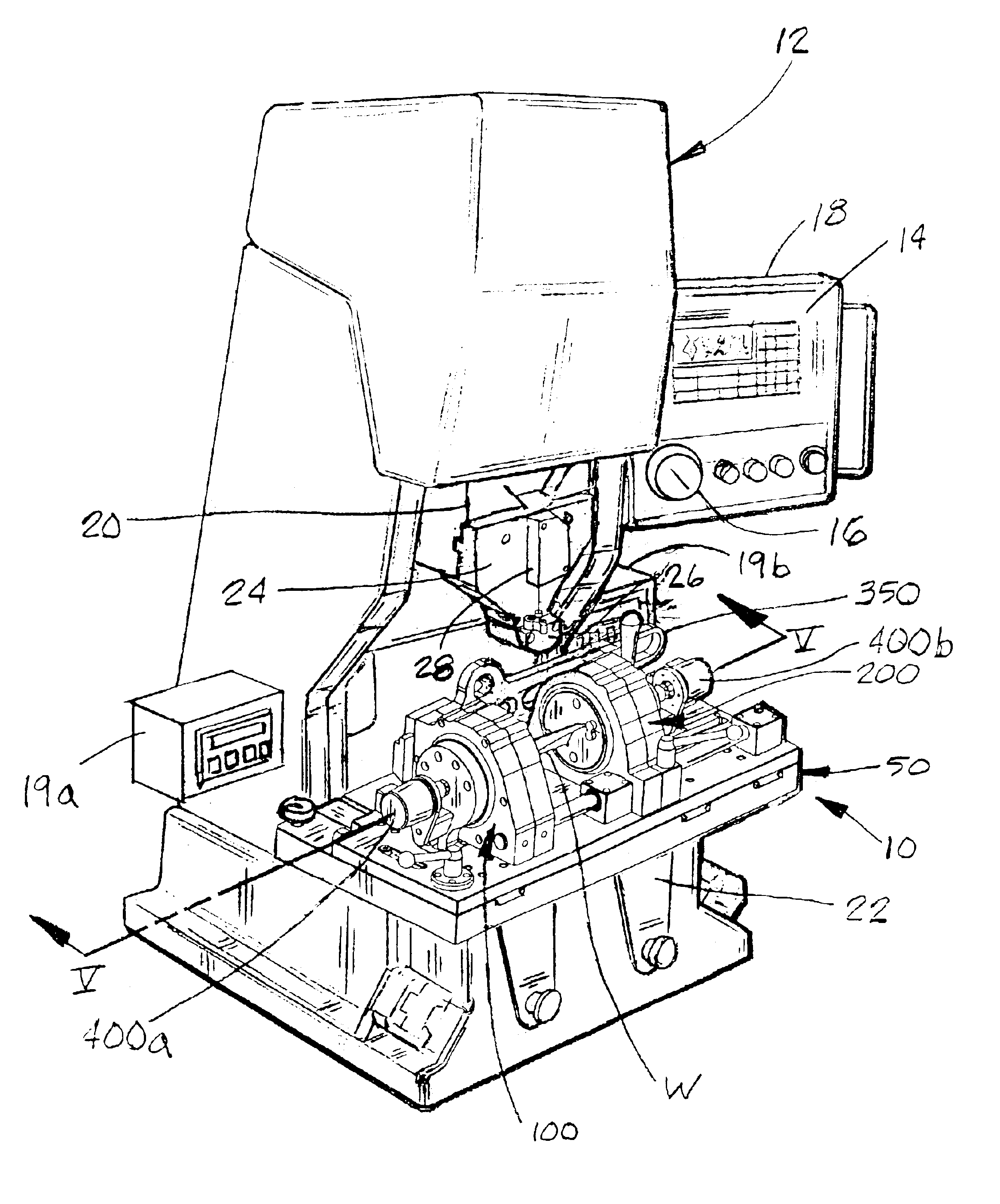
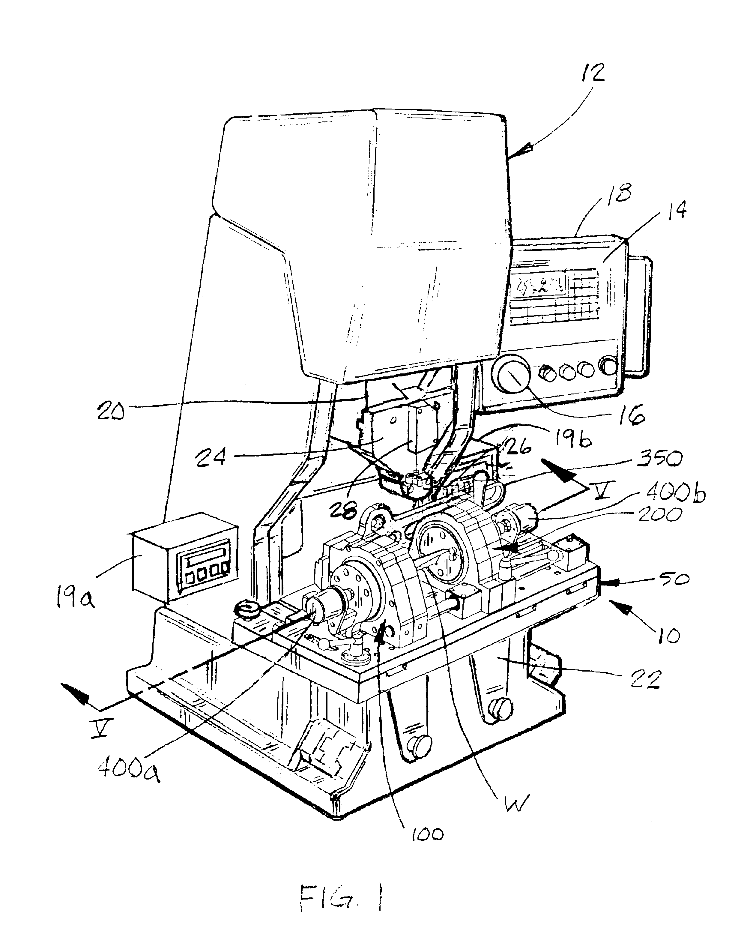
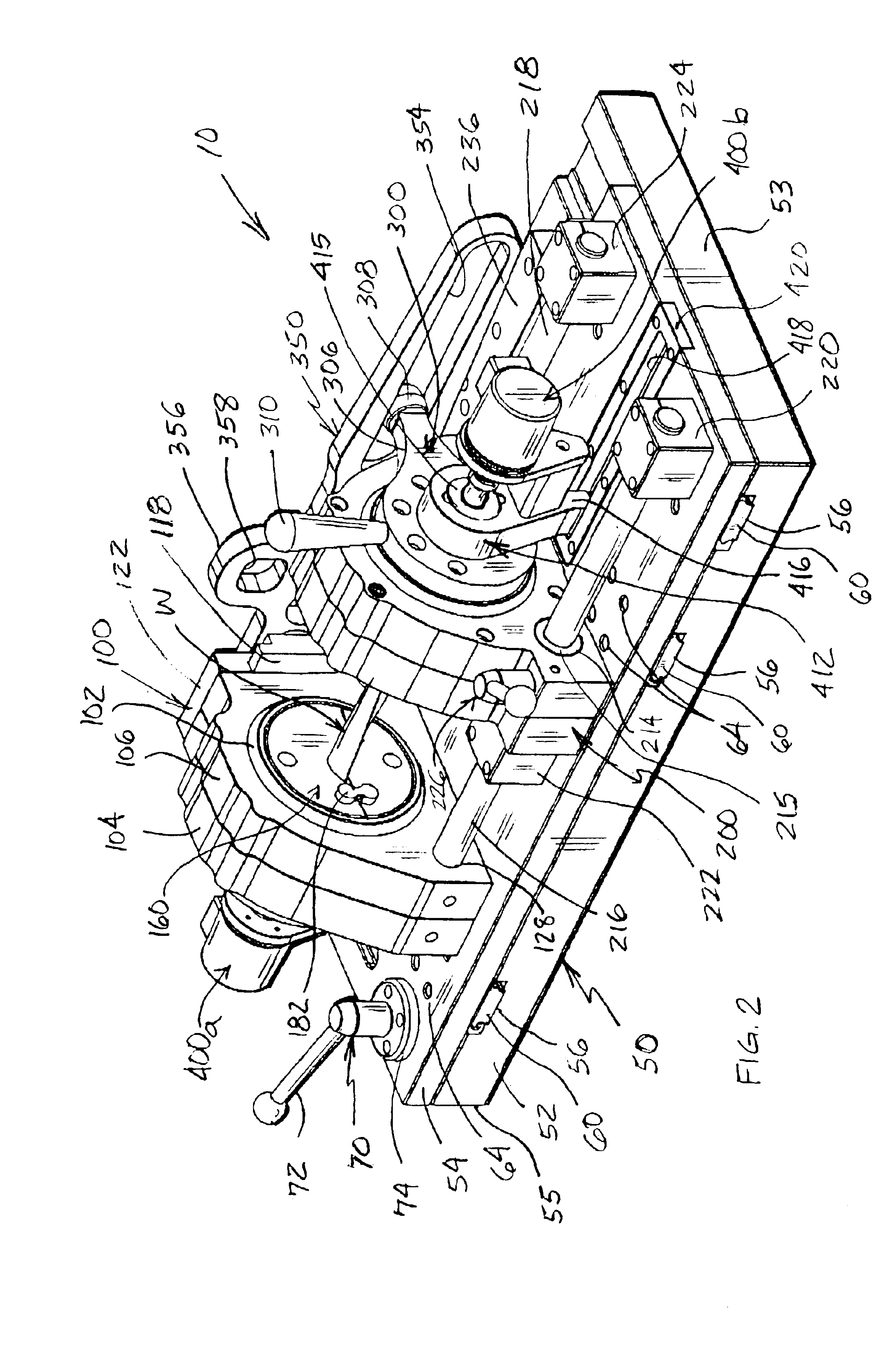
[0034]Referring now to the drawings in greater detail, FIG. 1 illustrates the apparatus or fixture 10 for holding a workpiece such as an investment cast turbine blade or the like in position on a press 12 for engagement and operation by the press for bow or straightening correction and / or rotational or twist correction of the workpiece. Preferably, press 12 is of the type sold under the trademark PRO ACTIVE® by ProEnterpriz LLC of Grand Haven, Mich. and is a bench-top, servo-driven press incorporating a programmable control the input for which is accessed by keypad 14 or electronic handwheel 16 on an operator console 18. Press 12 further includes a reciprocable ram 20 and a workpiece support area 22 beneath ram 20 which receives fixture 10 as is more fully described below. Preferably, two digital displays 19a, 19b are mounted on the press. Each digital display is preferably a type MA 47 electronic display available from Siko Products of Dexter, Mich. In addition, ram 20 preferably h...


PUM

PropertyMeasurementUnit
Areaaaaaaaaaaa
Distanceaaaaaaaaaa

Abstract

A fixture for supporting a workpiece such as a cast turbine blade allows bending and / or twist correction of the workpiece with the movable ram of a press. The fixture includes a base and a pair of workpiece supports mounted at spaced locations on the base. A bearing such as a spherical swivel bearing is included in each workpiece support. Each bearing has a mount receiving a portion of the workpiece therein. When the workpiece is supported by the bearing mounts along a support axis, and is engaged by the press ram intermediate the workpiece supports for bending correction, the bearings and workpiece can move in at least one plane including the support axis. Preferably, the bearings also allow rotational movement about the support axis, while a rotation imparting member allows twist correction by rotational movement of one bearing and the workpiece portion therein with respect to the other bearing which is restricted from rotating.

Description

FIELD OF THE INVENTION[0001]The present invention relates to apparatus for holding workpieces, and especially metallic workpieces, during mechanical correction of out-of-tolerance dimensions by bending, twisting and / or both bending and twisting following initial casting or other forming processes such as heat treating. More particularly, the invention relates to a fixture for supporting a workpiece on a press for straightening / bending or twist correction or both of the workpiece in a precisely controlled manner.BACKGROUND OF THE INVENTION[0002]In the manufacture of metal products and parts, a common production method is to cast such products or parts from molten metal. A particular form of casting is the manufacture of investment castings such as turbine blades for gas turbine generators, jet engines, or the like. Such casting processes create raw castings which are often out of tolerance from required specifications, i.e., castings that fail to meet necessary dimensional ranges for...

Claims


Application Information

Patent Timeline
IPC IPC(8): B21D11/14B21D11/00B21D3/16B21D3/00B21D3/10
CPCB21D3/10B21D3/16B21D11/14B23P6/002
Inventor LAWRENCE, PHILLIP G.HOHMAN, FREDERICK W.BRAAK, JEFFREY R.
Owner PROENTERPRIZ
Learn More