
Cooling system for work machine
a cooling system and work machine technology, applied in the direction of machines/engines, fluid couplings, couplings, etc., can solve the problems of increasing the load imposed on the driving circuit, abnormal noise, increasing the cost of the system, etc., to reduce the discharge oil rate of the hydraulic pump, preventing the occurrence of peak pressure in the hydraulic circuit for driving the cooling fan, and reducing the effect of the increase of the load
- Summary
- Abstract
- Description
- Claims
- Application Information
AI Technical Summary
Benefits of technology
Problems solved by technology
Method used
Image

Examples
Embodiment Construction
[0016]Referring now to the accompanying drawings, a cooling system for a work machine will be concretely described according to a preferred embodiment of the invention.
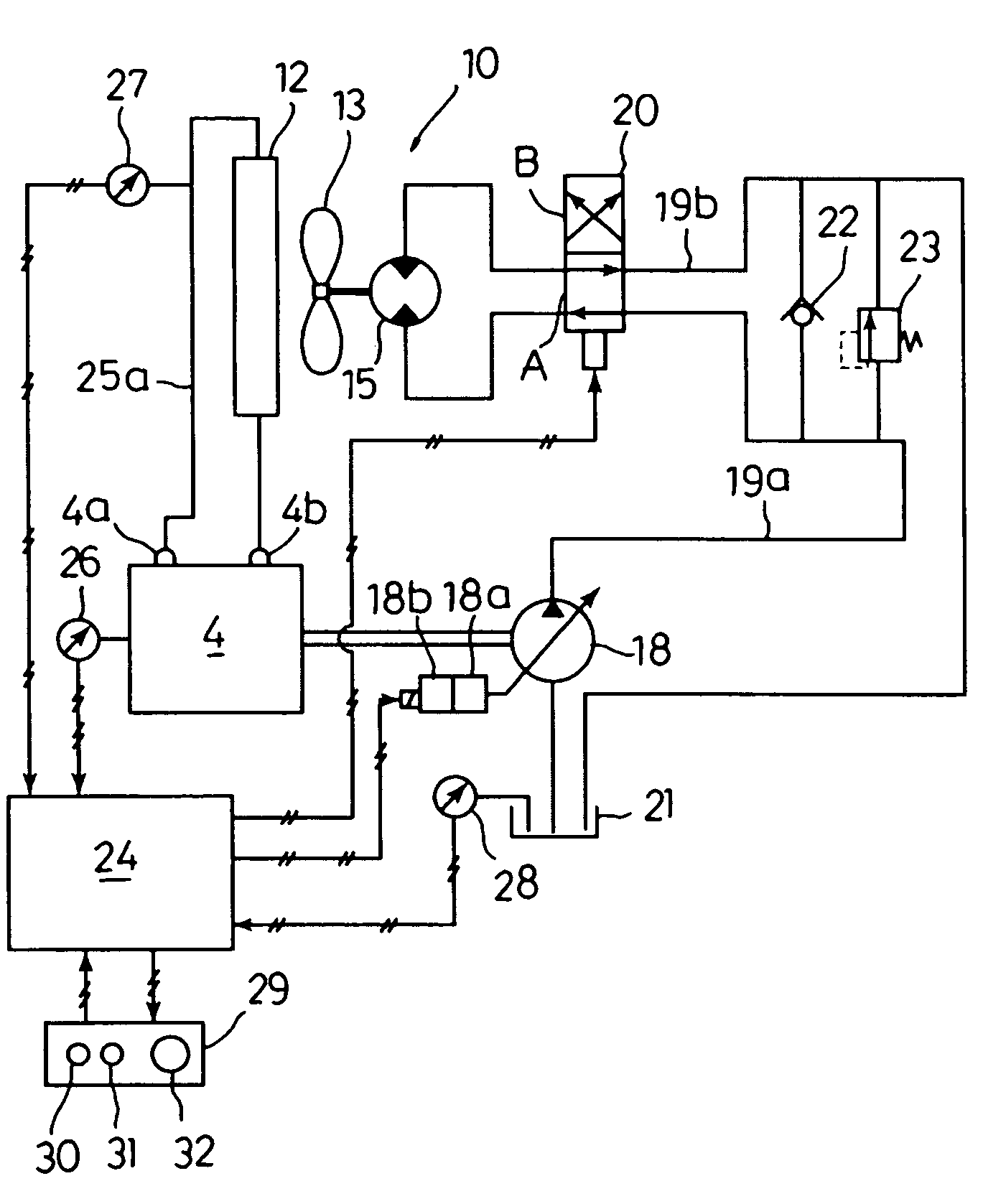
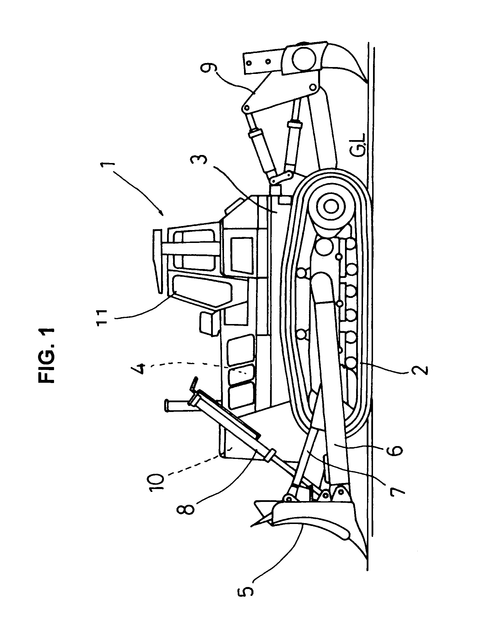
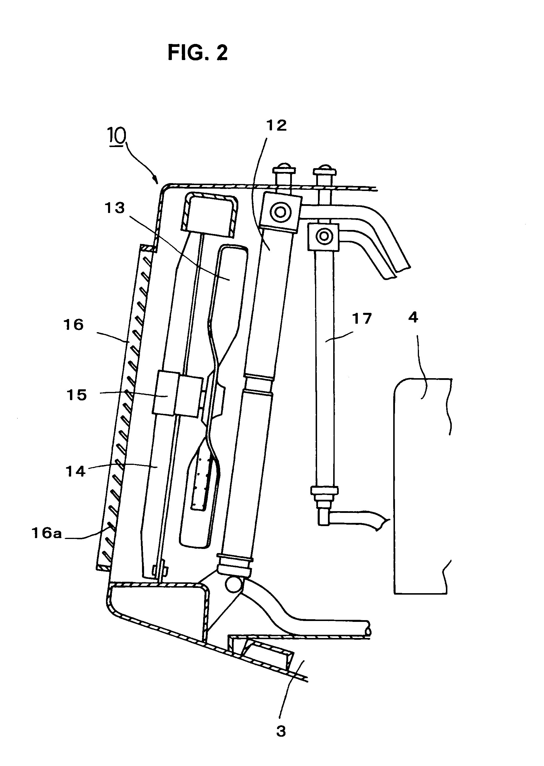
[0017]FIG. 1 shows a schematic side view of a bulldozer according to one embodiment of the invention. FIG. 2 is a schematic structural diagram of a cooling system incorporated in the bulldozer according to the embodiment.
[0018]In a bulldozer 1 of this embodiment, an engine 4 is mounted on an upper front part of a vehicle body 3 equipped with a track-type machine undercarriage 2 as shown in FIG. 1. Placed in front of the engine 4 is a cooling system 10 for cooling the engine 4. At a position in front of the vehicle body 3, a blade 5 is supported by frames 6 at its right and left sides so as to be operable by a tilt cylinder 7 and a lift cylinder 8. A ripper 9 is disposed behind the vehicle body 3 and an operator's cab 11 is provided at a central position slightly closer to the rear.
[0019]As shown in FIG. 2, the cooling...
PUM
 Abstract
Description
Claims
Application Information