Dual conveyor product conveying and accumulation system

a technology of product conveying and accumulation system, which is applied in the direction of conveyor parts, mechanical conveyors, storage devices, etc., can solve the problems of unrestricted product movement, disruption at a downstream location, and saving substantial time and expens

Active Publication Date: 2005-11-01
GARVEY CORP
View PDF5 Cites 31 Cited by
  • Summary
  • Abstract
  • Description
  • Claims
  • Application Information

AI Technical Summary

Benefits of technology

[0009]It is thus the object of the present invention to provide additional flexibility and alternatives for product conveying and accumulation systems by the use of uniquely configured dual conveyors for these systems.

Problems solved by technology

It is not uncommon that, during this process, there may be a disruption at a downstream location caused by a malfunction of machinery, some constraining problem, or other circumstance which prevents downstream machine from accepting products.
Continued operation of production upstream may result in the build-up of line back pressure which could cause a further problem in permitting the unrestricted movement of products.
Such a system also saves the substantial time and expense which would result in having to shutdown and then restart the entire system, if no accumulator was otherwise available.
However, these systems have significant disadvantages.
If the products are stored in single file, the amount of storage is minimal and the build-up of line pressure can be problematic for the downstream machinery, as well as the products, due to damage.
If products are stored inline and en masse, the amount of storage is increased, however, the line pressure increases as well and the added requirement of putting the products back into single file is required.
This creates the possibility of lost production due to jamming in the single filer.
This is almost always done en mass and therefore has the same inherent problems with line pressure and single filing requirements as inline storage devices.
However, due to the planar surfaces being adjacent to each other and the requirement that the products reverse direction at either end of the storage device, there are limitations to the size shape and speed of the products which can be stored on such a device.
Product instability limits the application of these devices.
Another factor, which limits the use of these devices is the noise and label damage generated by product-to-product contact during the re-circulating process.
Products such as larger glass containers and the like create noise levels which are not acceptable in normal production environments.

Method used


Image

  • Dual conveyor product conveying and accumulation system
  • Dual conveyor product conveying and accumulation system
  • Dual conveyor product conveying and accumulation system

Examples


Embodiment Construction

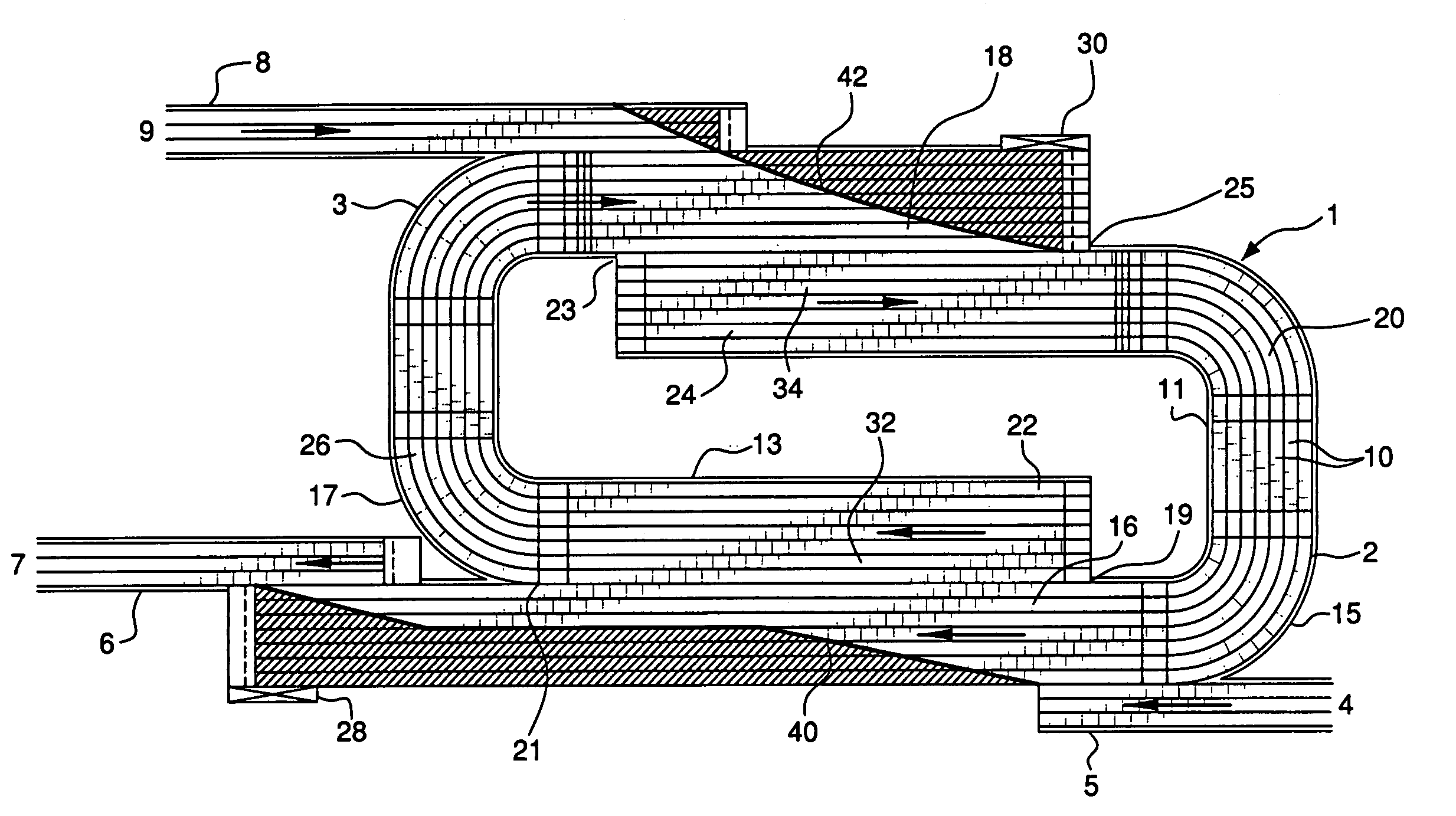
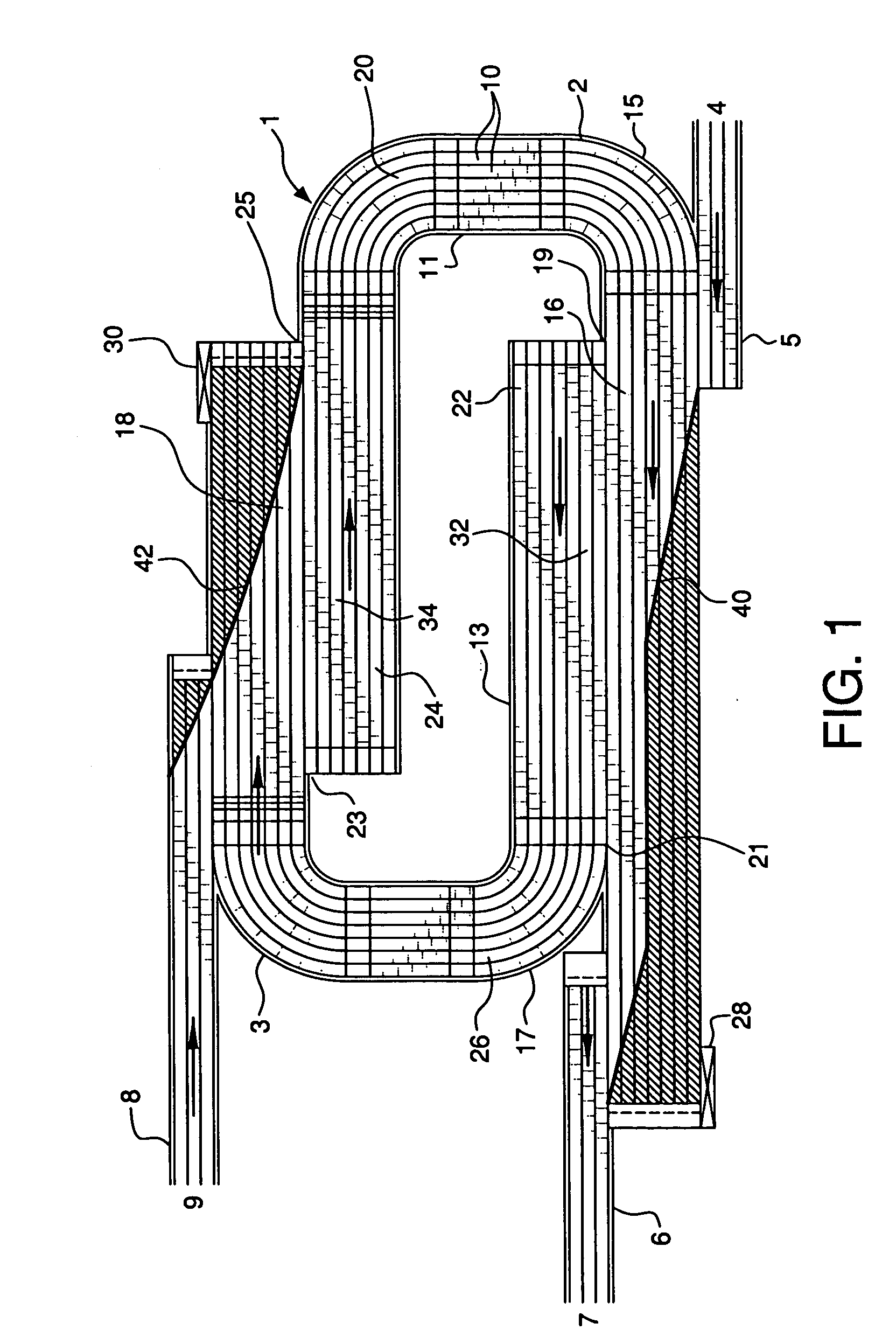
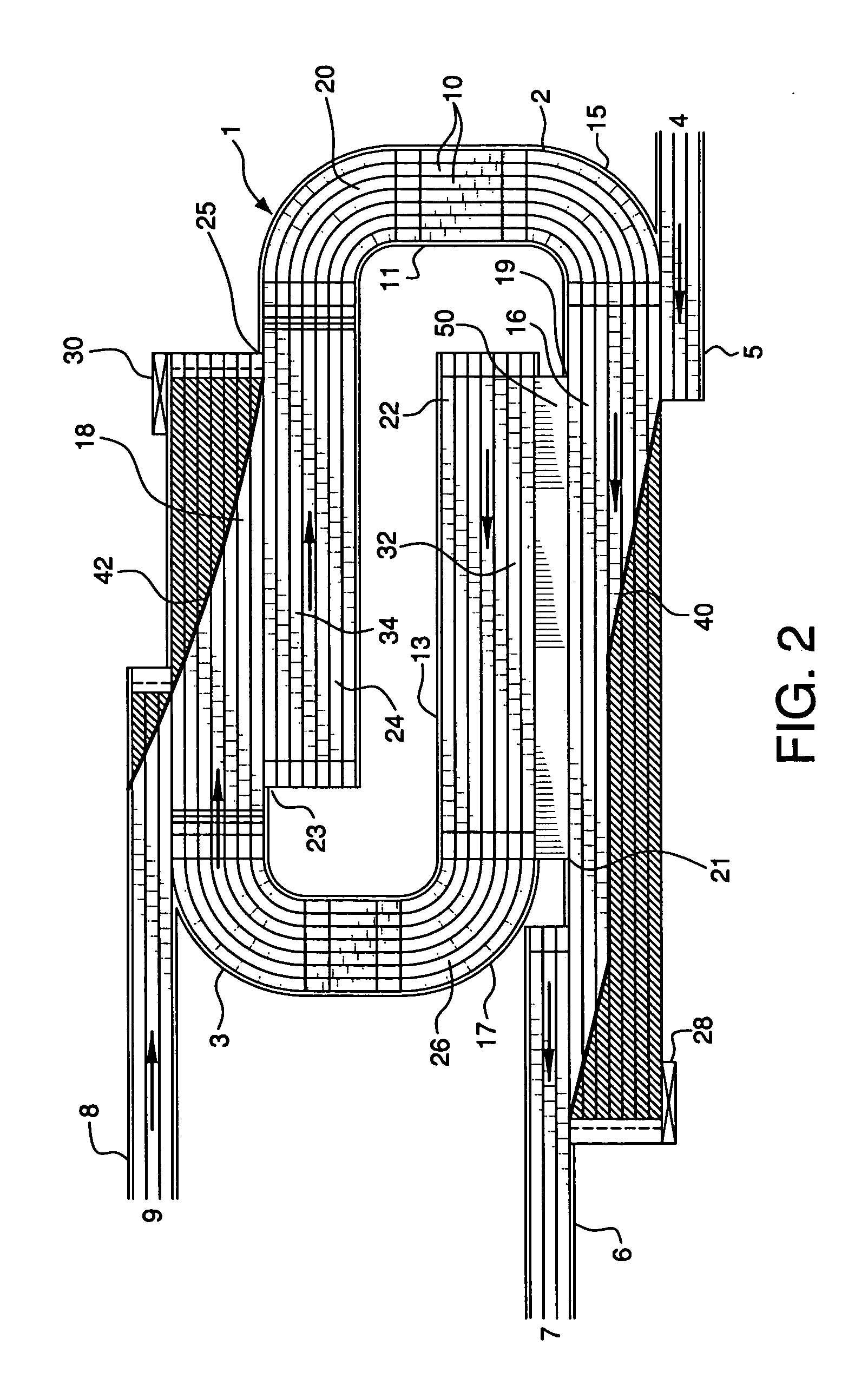
[0021]The product conveying and accumulation system 1 of the present invention comprises separate, U-shaped conveyors 2 and 3 which are configured to assist in the movement of products from an upstream location or station designated at 4, via conveyor 5. Conveyor 6 is configured to move products from system 1 to a downstream location, designated as 7. Conveyor 8, leading from upstream location 9, is shown to evidence that there may be alternate placement of conveyors in system 1 for the transport of products to and from the system. The invention is not deemed to be restrictive as to the positioning and configurations of those conveyors which provide products to system 1 from upstream to downstream destinations.

[0022]Conveyors 2 and 3 are constructed of interlocked segments 10 which are well known in the industry. Conveyor 2 comprises conveyor straightaway sections 16 and 18 which are parallel to each other and are interconnected by curved end conveyor section 20. Conveyor 3 comprise...


PUM


Abstract

A product conveying and accumulation system employs at least one product delivery conveyor which transports products from an upstream location and another conveyor which delivers products to a downstream location. Dual U-shaped accumulator conveyors in the system are positioned to accept upstream products from the delivery conveyors and to transport the products to the downstream conveyor. The dual conveyors each have straightaway conveyor sections which are aligned parallel to each other. Accumulator sections are formed at these parallel alignments. In one configuration, the two straightaway sections of one of the dual conveyors are parallel to and in adjacent alignment with the straightaway sections of the other of the dual conveyors. In another configuration, the straightaway section of one of the dual conveyors is parallel to and in adjacent alignment with one straightaway section of the other conveyor, and the other straightaway sections of the two conveyors are parallel to and in spaced relation to each other. This permits adjustment of the spacing and angle between an accumulator section of these conveyors.

Description

BACKGROUND OF THE INVENTION[0001]Product accumulation systems are routinely used in conjunction with conveyors for the storage and accumulation of products which are fed from an upstream source onto conveyors. In the normal operation of this type system, products are placed on a conveyor at the upstream location, for instance at one operational station, and then transported to a downstream location by conveyor where the next step in the manufacture or distribution of the products is to be accomplished.[0002]It is not uncommon that, during this process, there may be a disruption at a downstream location caused by a malfunction of machinery, some constraining problem, or other circumstance which prevents downstream machine from accepting products. Continued operation of production upstream may result in the build-up of line back pressure which could cause a further problem in permitting the unrestricted movement of products. However, if such a disruption is one which can be addressed ...

Claims


Application Information

Patent Timeline
Patent Type & Authority Patents(United States)
IPC IPC(8): B65G37/00B65G47/51B65G47/68
CPCB65G47/5145B65G47/684
Inventor GARVEY, MARK C.
Owner GARVEY CORP
Why Eureka
Try Eureka