Subcutaneous access port

a subcutaneous access and port technology, applied in the field of vascular access apparatuses to the living body, can solve the problems of limiting treatment options, worsening prognosis, and thrombosis of the vessel, and achieve the effects of increasing the filament strike area, short overall height, and reducing the risk of strok

Inactive Publication Date: 2005-11-01
ALPHAPORT
View PDF17 Cites 24 Cited by
  • Summary
  • Abstract
  • Description
  • Claims
  • Application Information

AI Technical Summary

Benefits of technology

[0015]A greatest distance between the walls is preferably at least five times greater than a height of the walls from the plate, so that the port provides a relatively large filament strike area, yet has a relatively short overall height. In addition, a greatest distance between the first and the second ends of the plate is also preferably at least five times greater than the height of the walls, to further increase the filament strike area. The large strike area of the presently disclosed port allows for multiple skin and tissue puncture sites along the port's length, yet the relatively short height of the port minimizes tension on the insertion wound of a patient.

Problems solved by technology

However, repeat cannulation of superficial vessels has been shown to result in vessel thrombosis, and in case of hemodialysis graft cannulation, access stenosis and the formation of pseudoaneurisms.
A patient's accessible vessels can quickly be eliminated by repeat direct cannulation during the course of some aggressive treatment regimens, limiting treatment options and worsening prognosis.
While catheters allow repeat access with a reduced risk of vessel thrombosis, they suffer from a number of significant drawbacks.
Aside from being unsightly and prone to inadvertent withdrawal, catheters often have complications with infection.
One significant limitation of the port 10, however, is in the strike area, or the region that the medical professional attempting access must hit with the accessing filament to enter the funnel-shaped entrance orifice 14.
Repeat trauma to tissue can lead to devascularization and necrosis, creating a potential site for infection.

Method used


Image

  • Subcutaneous access port
  • Subcutaneous access port
  • Subcutaneous access port

Examples


Embodiment Construction

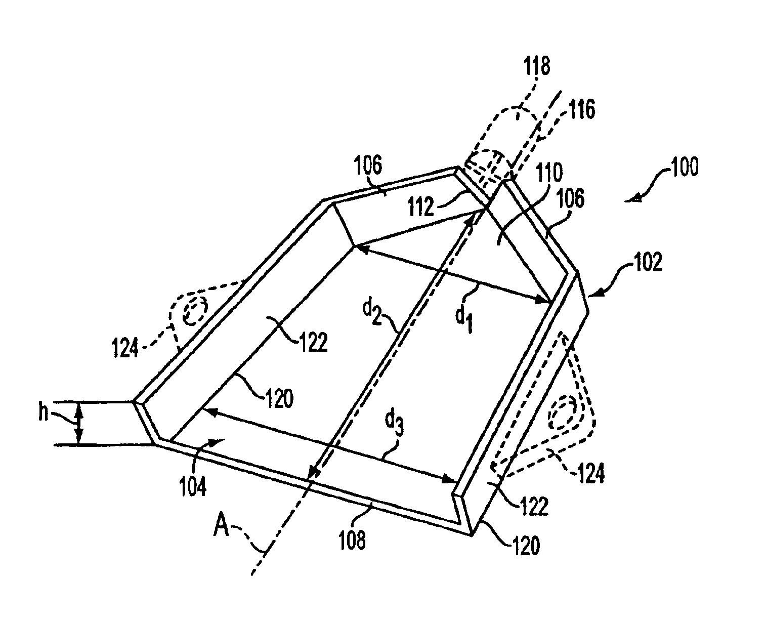
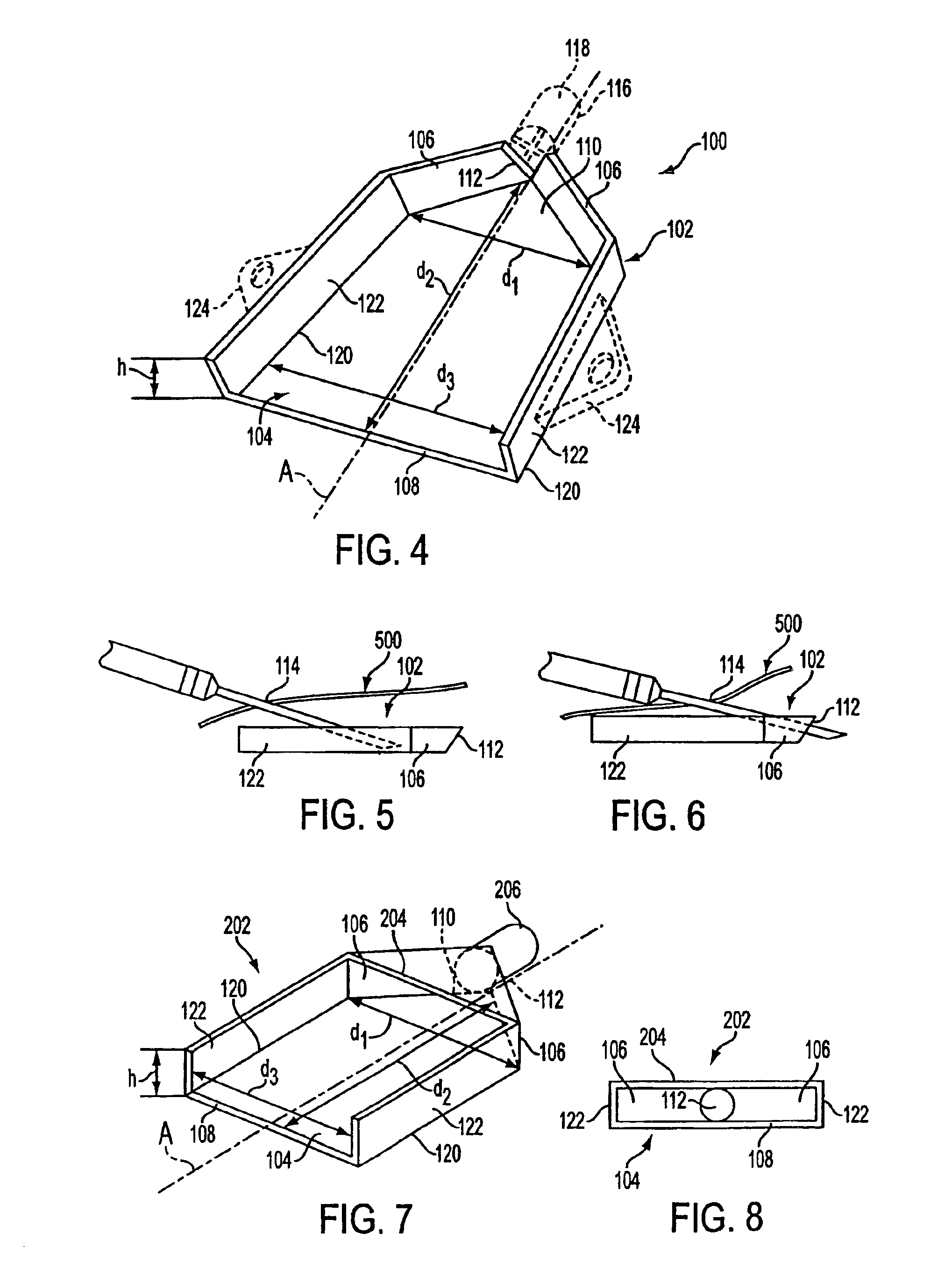
[0036]Referring to FIG. 4, the present disclosure provides an implantable patient access device 100 including a port 102 for receiving and guiding a filament, such as a needle, into an entry region 112 of the implantable device. The port 102 includes a plate 104 for receiving a filament, and at least two walls 106 extending upwardly from the plate 104. In general, the walls 106 are shaped and positioned to guide a filament moving between opposing first and second ends 108, 110 of the plate 104 towards the entry region 112 defined between the walls 106 and located substantially at the second end 110 of the plate 104. In the particular embodiment shown, a distance between the walls 106 decreases monotonically towards the entry region 112, although a port constructed in accordance with the present disclosure is not limited to a monotonically decreasing distance between the walls.

[0037]In addition, a greatest distance “d1” between the walls 106, which in the present embodiment correspon...


PUM


Abstract

An implantable access device including a port for receiving and guiding a filament, such as a needle, into an entry region of the device. The port includes a plate for receiving a filament, and at least two walls extending upwardly from the plate. The walls are shaped and positioned to guide the filament moving between opposing first and second ends of the plate through an entry region defined between the walls at the second end of the plate. Preferably, a greatest distance between the walls is at least five times greater than a height of the walls, so that the port provides a large filament strike area, yet has a small overall height. In addition, a greatest distance between the ends of the plate is also preferably at least five times greater than the height of the walls, to further increase the filament strike area without increasing height.

Description

CROSS-REFERENCE TO RELATED APPLICATION[0001]The present application claims priority from co-pending provisional U.S. Patent Application Ser. No. 60 / 197,191, filed Apr. 14, 2000, which is incorporated herein by reference in its entirety.FIELD OF THE DISCLOSURE[0002]The present disclosure generally relates to an apparatus for providing vascular access to a living body. More particularly, the disclosure relates to an improved needle-receiving port allowing repeated subcutaneous access to a region within the body of a patient.BACKGROUND OF THE DISCLOSURE[0003]During a course of medical treatment, it may be necessary to gain repeat access to specific sites, devices, tissues, or fluids within the body of a patient. This may be effected for the temporary or sustained infusion of various therapeutic agents, the removal and treatment of fluids, the injection of contrast agents, as well as the insertion of various treatment devices such as fiber-optic cameras and light sources, ultrasound pro...

Claims


Application Information

Patent Timeline
Patent Type & Authority Patents(United States)
IPC IPC(8): A61M39/02A61M37/00
CPCA61M39/0208A61M2039/0081
Inventor ADANIYA, GEORGEFENTON, JR., PAUL V.
Owner ALPHAPORT
Why Eureka
Try Eureka