Color translating UV microscope

a microscope and color technology, applied in the field of color translation microscopes, can solve the problems of high operating and maintenance burden and cost, all prior art attempts failed, and system mediocrity

Inactive Publication Date: 2005-11-01
1192062 ALBERTA
View PDF28 Cites 25 Cited by
  • Summary
  • Abstract
  • Description
  • Claims
  • Application Information

AI Technical Summary

Benefits of technology

[0009]It is an object of the present invention to provide a novel color translati...

Problems solved by technology

It is believed that all these prior art attempts failed due to the complex nature of the solutions attempted, the attendant costs and the high operating and maintenance burden and costs.
The results from these systems were mediocre at best due to the delay in image availability in the photographic processes and due to the low resolution and long integration times of the video solutions available at the time the work was carried out.
This reference suffers from disadvantages in that, for example, it needs high power UV illumination to provide sufficient illumination to the UV video camera which will be detrimental to the sample, it does not combine multiple three UV images from the same camera created with suc...

Method used


Image

  • Color translating UV microscope
  • Color translating UV microscope
  • Color translating UV microscope

Examples


Embodiment Construction

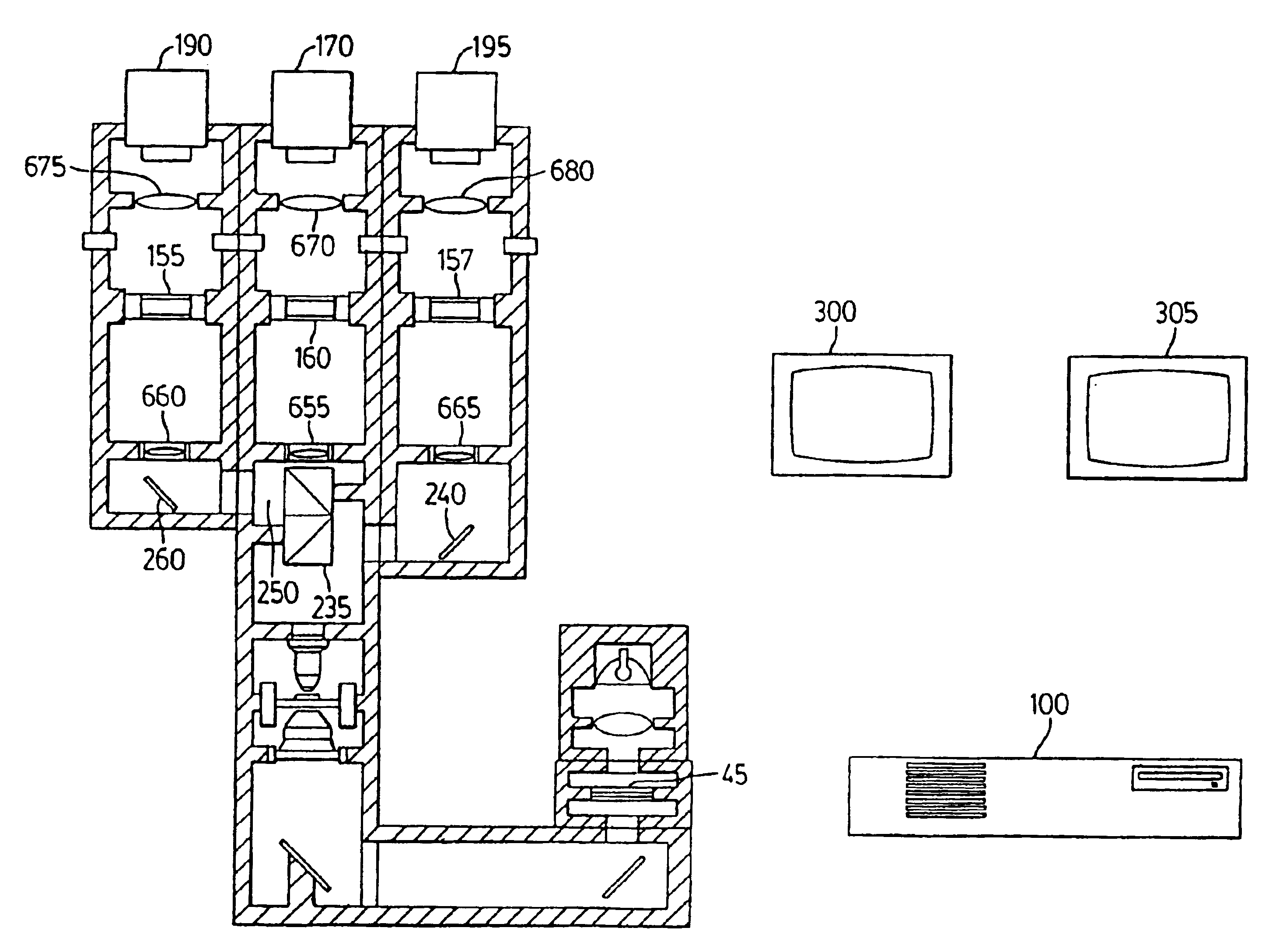
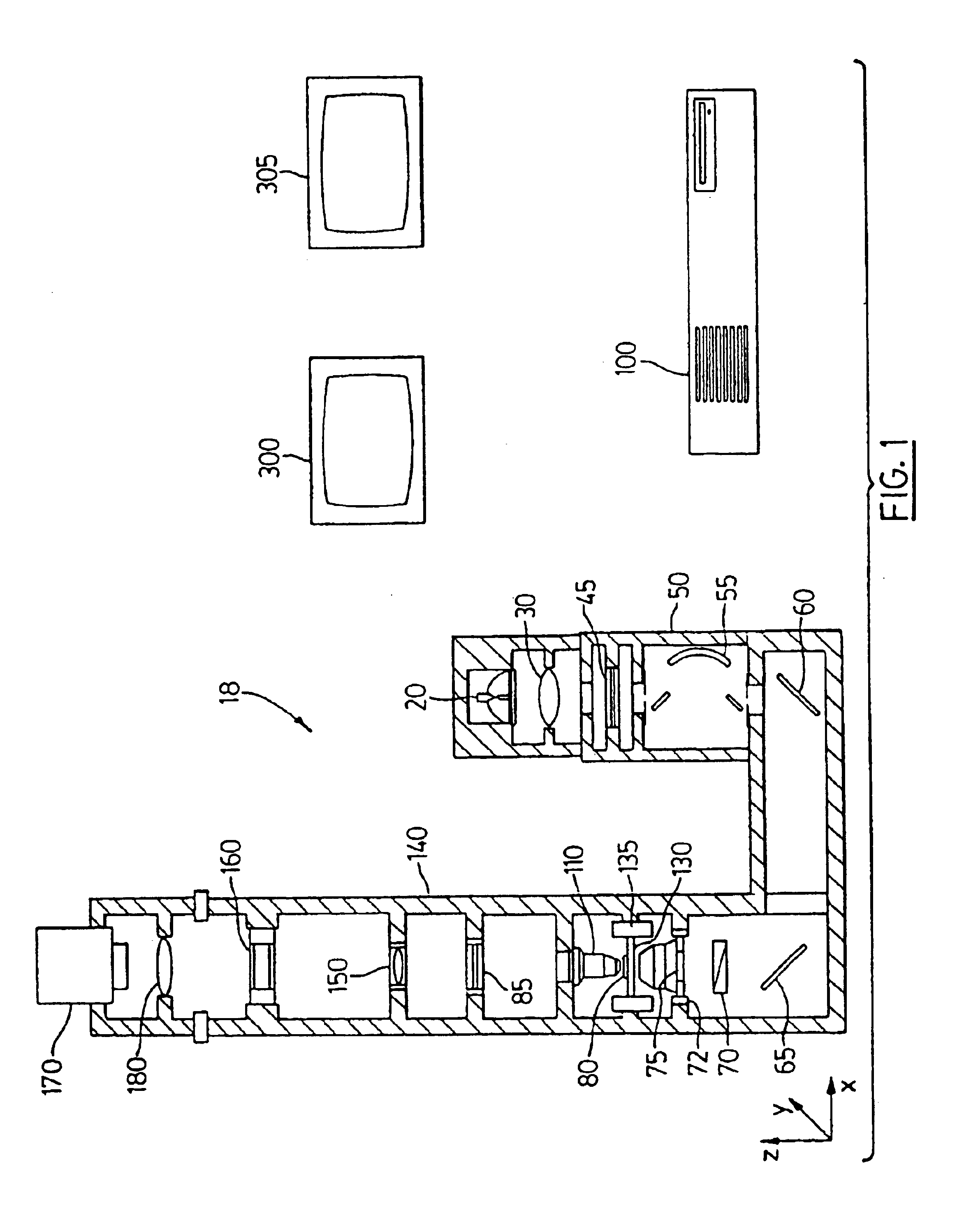
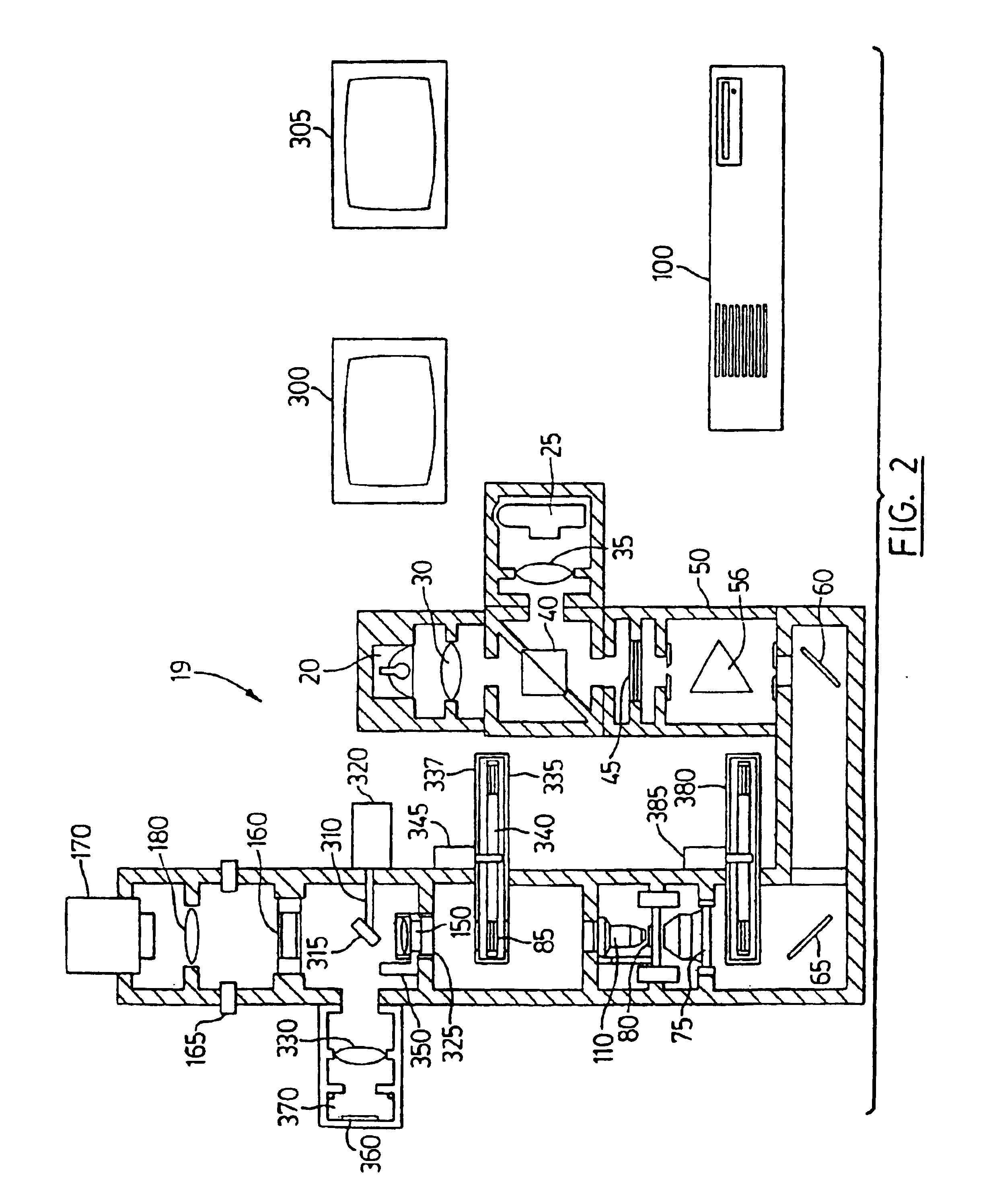
[0045]This invention stems from the desire to provide a powerful new research and clinical tool which advances the state of the art in microscopes for living or dynamic sample microscopy while maintaining the sample in a state as close as possible to it's normal conditions. In the discussion below, the following abbreviations are employed with these definitions: UV—light from the spectral region of wavelengths shorter than four hundred nanometers; visible—light from the spectral region from four hundred to seven hundred nanometers; IR—light from infrared, the spectral region of wavelengths longer than seven hundred nanometers; NIR—light from near infrared, the spectral region from seven hundred to three thousand three hundred nanometers; and a subset of IR and DIC—differential interference contrast, a means of enhancing image contrast in microscopy. The terms sample denotes the particular thing being imaged by the microscope and normally placed on a slide in a stage or holder in the...


PUM


Abstract

A color translating UV microscope for research and clinical applications involving imaging of living or dynamic samples in real time and providing several novel techniques for image creation, optical sectioning, dynamic motion tracking and contrast enhancement comprises a light source emitting UV light, and visible and IR light if desired. This light is directed to the condenser via a means of selecting monochromatic, bandpass, shortpass, longpass or notch limited light. The condenser can be a brightfield, darkfield, phase contrast or DIC. The slide is mounted in a stage capable of high speed movements in the X, Y and Z dimensions. The microscope uses broadband, narrowband or monochromat optimized objectives to direct the image of the sample to an image intensifier or UV sensitive video system. When an image intensifier is used it is either followed by a video camera, or in the simple version, by a synchronized set of filters which translate the image to a color image and deliver it to an eyepiece for viewing by the microscopist. Between the objective and the image intensifier there can be a selection of static or dynamic switchable filters. The video camera, if used, produces an image which is digitized by an image capture board in a computer. The image is then reassembled by an overlay process called color translation and the computer uses a combination of feedback from the information in the image and operator control to perform various tasks such as optical sectioning and three dimensional reconstruction, coordination of the monochromater while collecting multiple images sets called image planes, tracking dynamic sample elements in three space, control of the environment of the slide including electric, magnetic, acoustic, temperature, pressure and light levels, color filters and optics, control for microscope mode switching between transmitted, reflected, fluorescent, Raman, scanning, confocal, area limited, autofluorescent, acousto-optical and other modes.

Description

CROSS-REFERENCE TO OTHER APPLICATIONS[0001]This application is a divisional patent application of U.S. patent application Ser. No. 09 / 402,467, filed Dec. 23, 1999, now U.S. Pat. No. 6,650,357 which application is a 371 of international patent application No. PCT / CA 98 / 00350 filed Apr. 9, 1998, which application claims priority from U.S. patent application Ser. No. 08 / 900,193 filed Jul. 25, 1997 and from U.S. Provisional Patent Application Ser. Nos. 60 / 044,247 and 60 / 041,855 filed Apr. 23, 1997 and Apr. 9, 1997, respectively. This application claims the benefit of all aforementioned applications, and incorporates all said applications herein by reference.FIELD OF THE INVENTION[0002]The present invention relates to a color translating microscope employing ultraviolet light in place of or in addition to visible and / or infrared light sources. More specifically, the present invention relates to a method and a microscope which determine and represent differential absorption, transmission,...

Claims


Application Information

Patent Timeline
IPC IPC(8): G01N21/64G02B21/16G01N21/65
CPCG01J3/10G01J3/32G01J3/36G01N21/6458G01N21/65G02B21/16H04N9/47G01N2021/6419G01N2021/6421G01N2021/6423G01N2021/656
Inventor RICHARDSON, TIM
Owner 1192062 ALBERTA
Why Eureka
Try Eureka