
Dynamic offset and feedback threshold

a feedback threshold and offset technology, applied in the field of computerimplementation and/or computerenabled, can solve the problems of random noise component of white noise and therefore relatively non-controllable, and achieve the effect of tighter control of feedback and feedforward variations, and non-controllability

Inactive Publication Date: 2005-11-01
APPLIED MATERIALS INC
View PDF435 Cites 80 Cited by
  • Summary
  • Abstract
  • Description
  • Claims
  • Application Information

AI Technical Summary

Benefits of technology

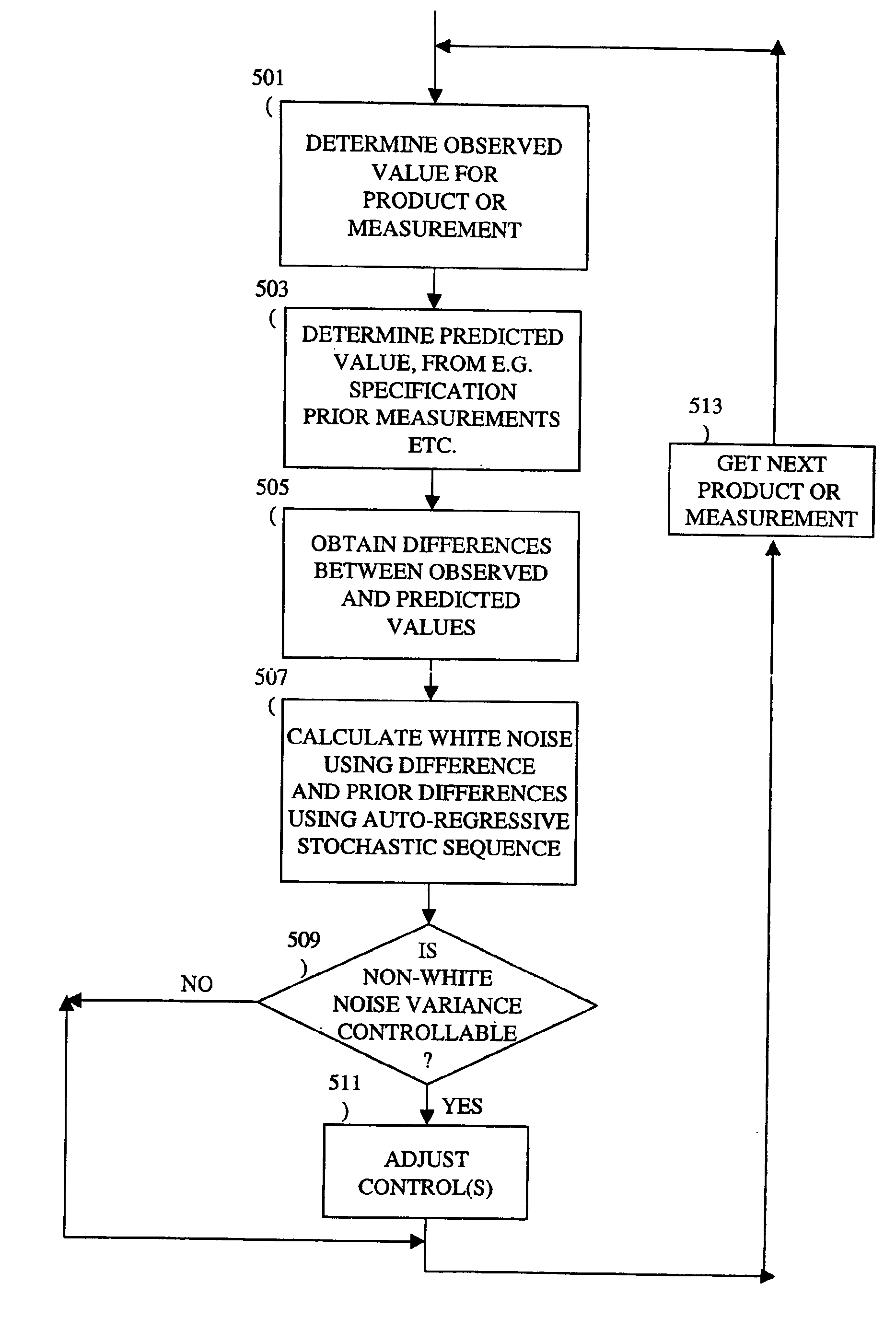
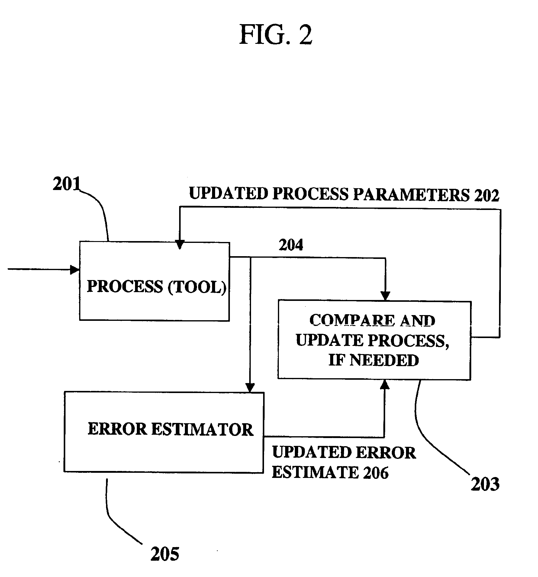
[0016]The present invention provides a way to determine the error within standard deviation that is caused by two components: a white noise component and a signal component (such as systematic errors). The white noise component is random noise and therefore is relatively non-controllable. The systematic errors, in contrast, may be controlled by changing the control parameters in a manufacturing process. A ratio between the two components is calculated autoregressively. Based on the ratio and using the observed or measured error (as, e.g., typically made over the course of several measurements), the actual value of the error caused by the white noise is calculated. The actual value of the error is then used in determining whether and how to change the control parameters of the manufacturing. The autoregressive stochastic sequence addresses the issue of real-time control of the effects of run-to-run deviations, and provides a mechanism that can extract white noise from the statistical process variance in real time. This results in an ability to provide tighter control of feedback and feedforward variations.

Problems solved by technology

The white noise component is random noise and therefore is relatively non-controllable.

Method used


Image

  • Dynamic offset and feedback threshold
  • Dynamic offset and feedback threshold
  • Dynamic offset and feedback threshold

Examples


Embodiment Construction

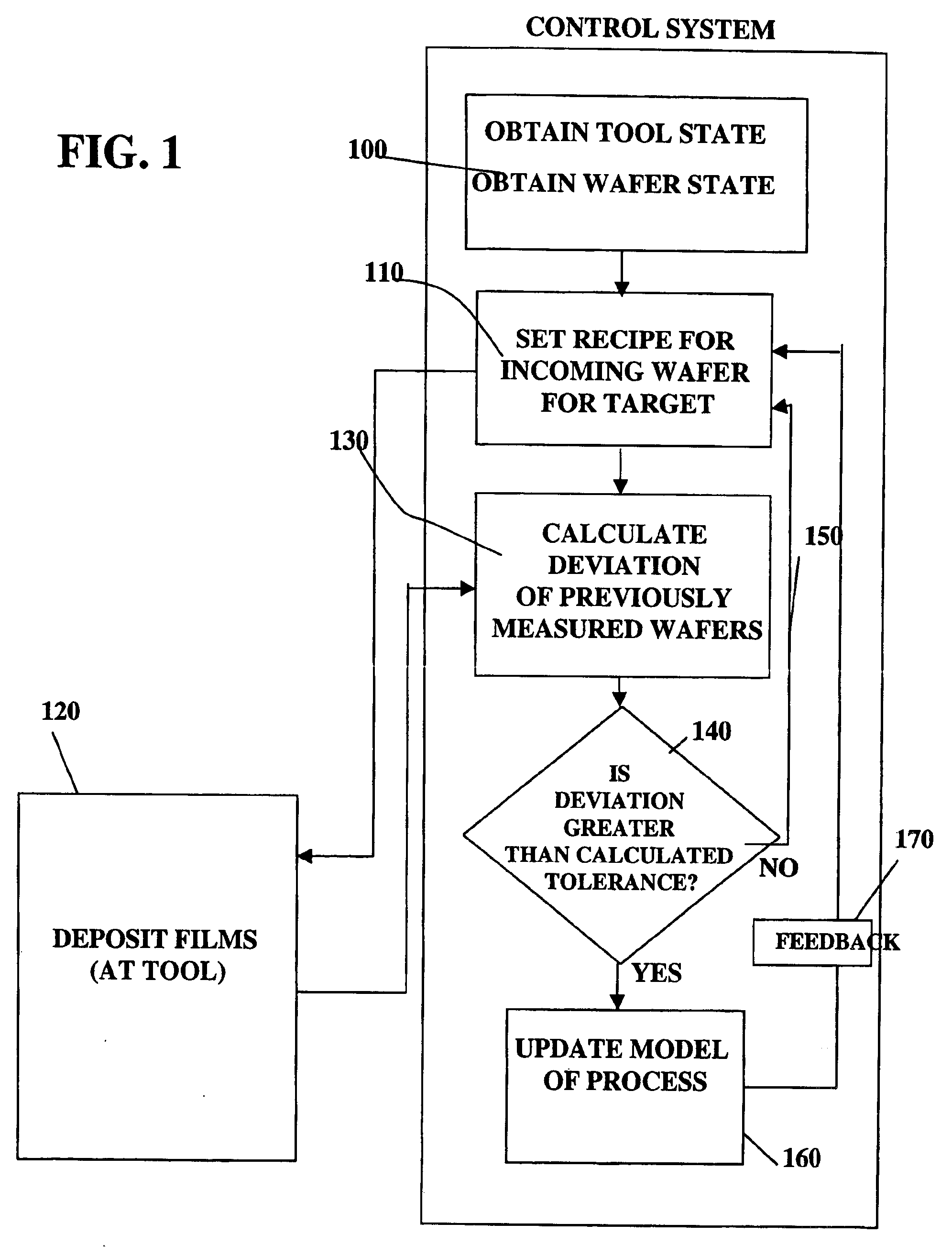
[0026]Process control is used in semiconductor manufacturing to maintain one or more characteristics of the product, e.g., a semiconductor wafer, to within acceptable and predictable ranges. In implementing process control, a model of the process is developed that predicts wafer characteristics for a given set of input conditions. A manufacturing recipe is obtained based in whole or in part on the model. A product characteristic of interest is monitored during processing, and variations in the product output from the target value are used to provide a feedback loop for updating the deposition recipe in the process control box, as is shown schematically in FIG. 1.

[0027]According to the processing flow diagram in FIG. 1, initial processing conditions (e.g., an initial tool state and initial wafer state) are identified that will provide a desired wafer property in step 100. The initial conditions may be determined empirically or by using the processing model. If a processing model is u...


PUM


Abstract

A method, system and medium are provided for enabling improved feedback and feedforward control. An error, or deviation from target result, is observed during manufacture of semi conductor chips. The error within standard deviation is caused by two components: a white noise component and a signal component (such as systematic errors). The white noise component is random noise and therefore is relatively non-controllable. The systematic error, in contrast, may be controlled by changing the control parameters. A ratio between the two components is calculated autoregressively. Based on the ratio and using the observed or measured error, the actual value of the error caused by the signal component is calculated utilizing an autoregressive stochastic sequence. The actual value of the error is then used in determining when and how to change the control parameters. The autoregressive stochastic sequence addresses the issue of real-time control of the effects of run-to-run deviations, and provides a mechanism that can extract white noise from the statistical process variance in real time. This results in an ability to provide tighter control of feedback and feedforward variations.

Description

CROSS-REFERENCE TO RELATED APPLICATIONS[0001]This application is related to co-pending application entitled “Improved Process Control By Distinguishing a White Noise Component of a Process Variance,” filed on even date herewith and incorporated by reference.BACKGROUND OF THE INVENTION[0002]1. Field of the Invention[0003]The present invention concerns computer-implemented and / or computer-enabled methods, systems, and mediums for enabling improved feedback and feedforward control during process control. More specifically, one or more embodiments of the present invention relate to run-to-run control, including determining offset and feedback threshold values during real-time process control, particularly in connection with semiconductor manufacturing.[0004]2. Description of the Related Art[0005]Detecting and controlling errors during a manufacturing process is an important goal. This is particularly true in connection with the process of manufacturing semiconductors. During the manufac...

Claims


Application Information

Patent Timeline
IPC IPC(8): G01N37/00G05B13/02G06F19/00G05B19/418
CPCG05B19/41875G05B2219/31103G05B2219/32187Y02P90/02
Inventor PAIK, YOUNG JEEN
Owner APPLIED MATERIALS INC
Learn More