Non-synchronized multiplex data transport across synchronous systems

a technology of multiplex data and synchronous systems, applied in the field of logic circuit emulation systems, can solve the problems of large clock skew, inability to reliably estimate, and inability to provide clock signals between plds separated by a relatively large distance (e.g., plds on circuit boards on different chassis)

Inactive Publication Date: 2005-11-01
MENTOR GRAPHICS CORP
View PDF17 Cites 20 Cited by
  • Summary
  • Abstract
  • Description
  • Claims
  • Application Information

AI Technical Summary

Benefits of technology

[0008]The present invention provides methods and systems for reliably transmitting data

Problems solved by technology

While this clock distribution scheme is conventional in an emulation circuit configured in PLDs in very close proximity (e.g., PLDs on a single circuit board, or on different circuit boards interconnected on a single backplane bus), such a clock signal cannot be provided between PLDs separated by a re

Method used


Image

  • Non-synchronized multiplex data transport across synchronous systems
  • Non-synchronized multiplex data transport across synchronous systems
  • Non-synchronized multiplex data transport across synchronous systems

Examples


Embodiment Construction

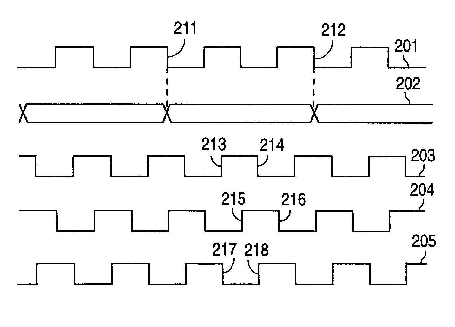
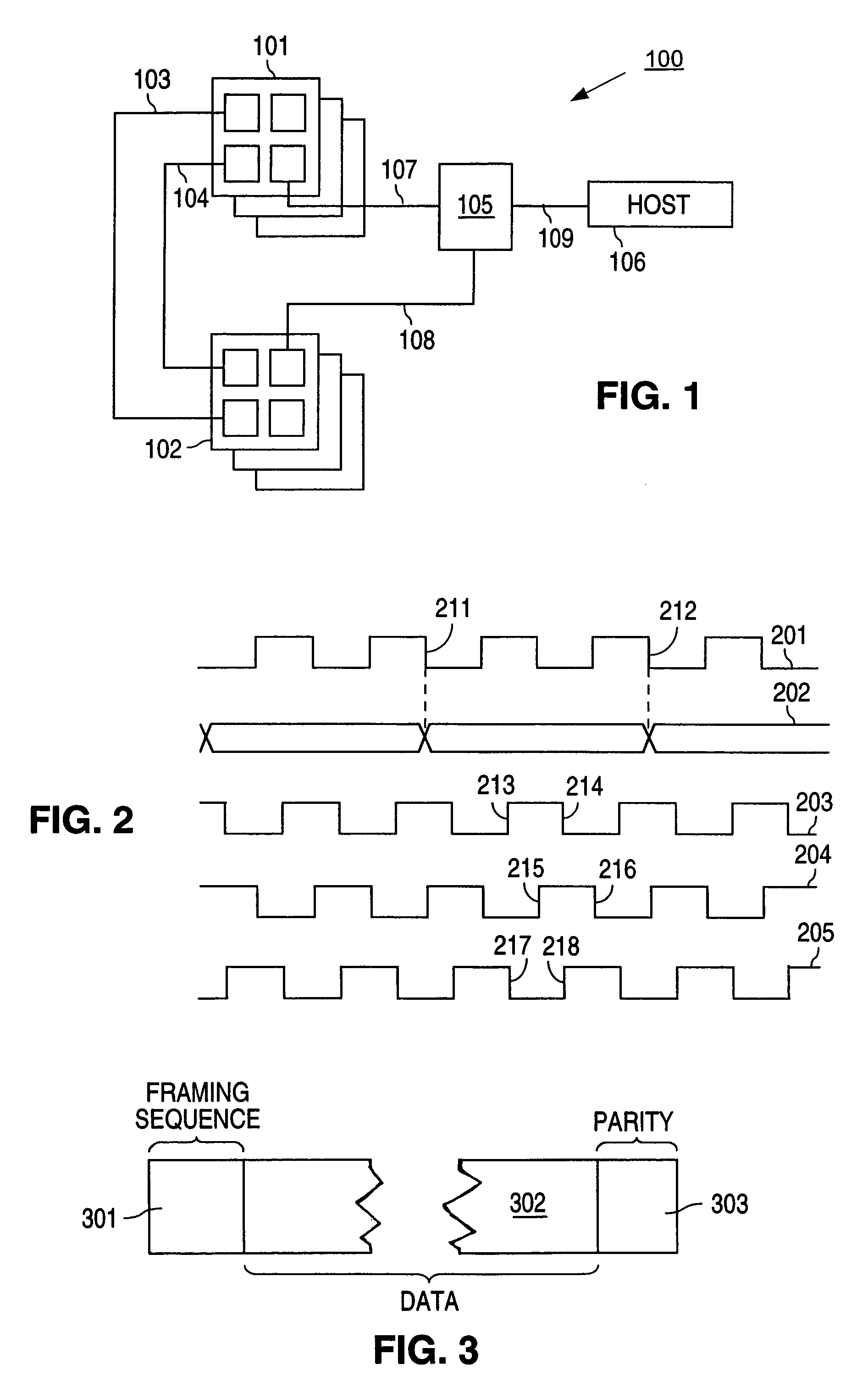
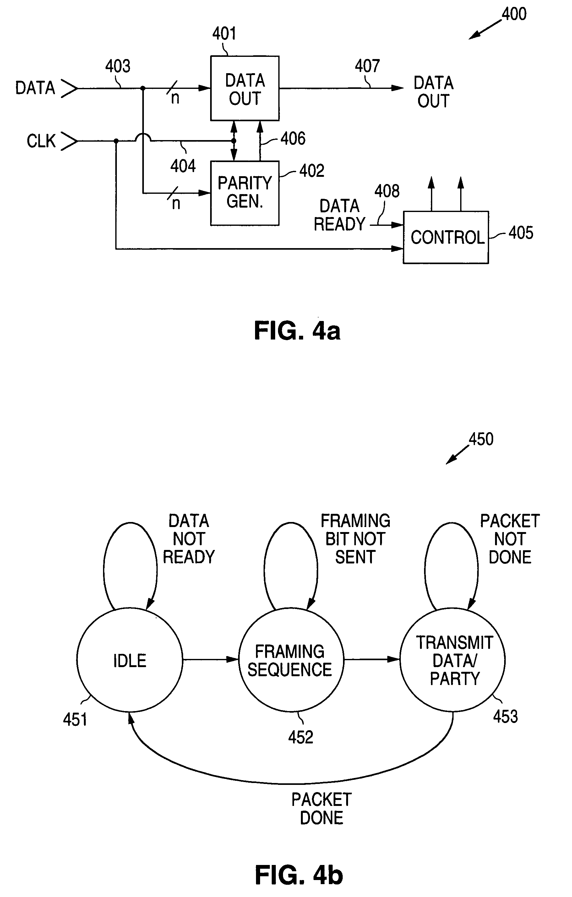
[0022]The present invention is applicable to an emulation system, such as that shown in FIG. 1. As shown in FIG. 1, emulation system 100 includes two groups of circuit boards 101 and 102, each group having a number of circuit boards populated by field programmable gate arrays (FPGAs) which can be configured by controller 105 to emulate a user circuit. Signals between circuit board groups 101 and 102 are provided over a number of wires, such as wires 103 and 104 shown in FIG. 1. Some of these signals can be signals in the emulation circuit configured in circuit board groups 101 and 102, and may be uni-directional or bi-directional. In this embodiment, circuit board groups 101 and 102 are housed in different equipment chassis. Controller 105 also controls the operation of circuit boards 101 and 102 and receives selected signals from the emulation circuit configured in circuit board groups 101 and 102. Terminals 107 and 108 represent, respectively, wires connecting logic signals from t...


PUM


Abstract

A method allows two substantially asynchronous system components of a logic emulation system to exchange data packets with reference to a clock signal of predetermined frequency. In one example, each bit is transmitted across the system components over two or more cycles of the clock signal. The reference clock signal can be distributed to the two system components from a common clock signal generator, or can be generated locally independently.

Description

BACKGROUND OF THE INVENTION[0001]1. Field of the Invention[0002]The present invention relates to logic circuit emulation systems. In particular, the present invention relates to providing data transport across practically asynchronous portions of a logic circuit emulation system.[0003]2. Discussion of the Related Art[0004]A typical emulation system for a large logic circuit is described, for example, in U.S. Pat. No. 5,761,484, entitled “Virtual Interconnections For Reconfigurable Logic Systems,” to Agarwal et al. Such an emulation system is often used during the development of an integrated circuit to simulate circuit operation and circuit performance. In such a system, the designer provides a logic netlist that is then partitioned by the emulation system for implementing an emulation circuit configured in a number of programmable logic devices (e.g., field programmable gate arrays or FPGAs). These programmable logic circuits (PLDs) are typically provided on one or more circuit boa...

Claims


Application Information

Patent Timeline
IPC IPC(8): G06F17/50
CPCG06F17/5027G06F30/331
Inventor SELVIDGE, CHARLES W.CROUCH, KENNETH W.KUDLUGI, MURALIDHAR R.HASSOUN, SOHA M. N.
Owner MENTOR GRAPHICS CORP
Why Eureka
Try Eureka