Supercharge Your Innovation With Domain-Expert AI Agents!

Method of designing integrated circuit having both configurable and fixed logic circuitry

Inactive Publication Date: 2005-11-01
XILINX INC
View PDF89 Cites 19 Cited by
  • Summary
  • Abstract
  • Description
  • Claims
  • Application Information

AI Technical Summary

Benefits of technology

[0013]This method may also include selecting a die size for the integrated circuit and designing the integrated circuit such that the configurable logic blocks and the at least one fixed logic input/output circuit fit within a targeted die size. Further, the method may include selecting a process for manufacturing of the integrated circuit, wherein the process involves a minimum dimension size for the integrated circuit and selecting a die size for the integrated circuit considering the process, the approximate number of configurable logic blocks and the at least one fixed logic input/outpu

Problems solved by technology

As such, the manufacturing expense of an FPGA is greater than that of an ASIC.
In addition, an FPGA requires significantly more printed circuit board space and consumes more power than an equally functional ASIC.
The integration of these two circuit types has left many in the art with very little direction on how to perform and to provide this combination of elements as desired by end users.

Method used


Image

  • Method of designing integrated circuit having both configurable and fixed logic circuitry
  • Method of designing integrated circuit having both configurable and fixed logic circuitry
  • Method of designing integrated circuit having both configurable and fixed logic circuitry

Examples


Embodiment Construction

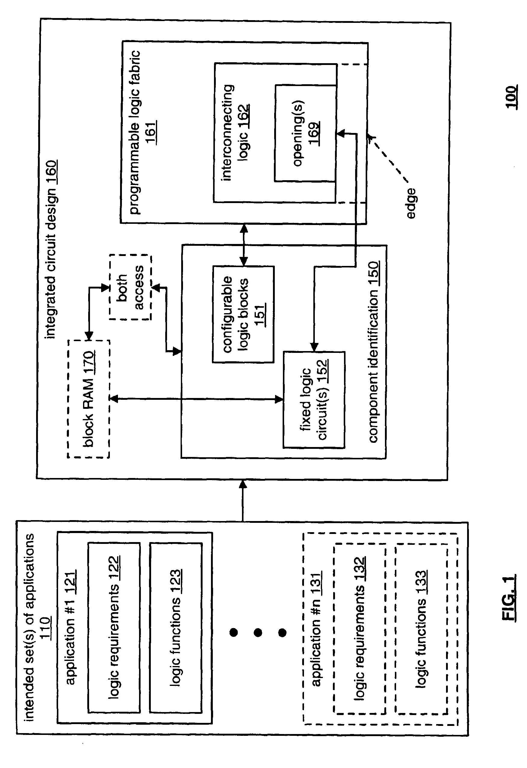
[0027]FIG. 1 is a system diagram illustrating an embodiment of method for designing an integrated circuit 100 by considering one or more intended sets of application in accordance with the present invention. A number of intended set(s) of applications 110 are identified and used to influence an integrated circuit design 160. The intended set(s) of applications 110 includes as few as one intended set(s) of applications and may include any number of intended set(s) of applications. The intended set(s) of applications 110 may be categorized as targeting a number of applications, as shown by an application #1121, . . . , and an application #n 131. If desired, each of the applications are further categorized as having logic requirements and logic functions. For example, the application #1121 is shown as having logic requirements 122 and logic functions 123. Similarly, the application #n 131 is shown as having logic requirements 132 and logic functions 133.

[0028]The integrated circuit des...


PUM


Abstract

A method for designing an integrated circuit having both fixed logic and programmable logic components. An intended set of applications for the integrated circuit is first identified. In addition, for each of the intended set of applications, the logic requirements are identified. An approximate number of configurable logic blocks and at least one fixed logic circuit are selected that, when combined to operate cooperatively, meet a substantial portion of the logic requirements and the logic functions of the intended set of applications. The method also involves designing the integrated circuit with the approximate number of configurable logic blocks arranged and interconnected to form a fabric that surrounds an opening, and inserting the at least one fixed logic circuit into the opening in the fabric. In addition, the method involves adding logic to the integrated circuit that interfaces the at least one fixed logic circuit to the fabric and input / output circuitry.

Description

BACKGROUND[0001]1. Technical Field[0002]The invention relates generally to the design of integrated circuits; and, more particularly, it relates to the design of integrated circuits having both fixed logic and programmable logic components.[0003]2. Related Art[0004]Programmable devices are a class of general-purpose integrated circuits that can be configured for a wide variety of applications. Such programmable devices have two basic versions, mask programmable devices, which are programmed only by a manufacture, and field programmable devices, which are programmable by the end user. In addition, programmable devices can be further categorized as programmable memory devices or programmable logic devices. Programmable memory devices include programmable read only memory (PROM), erasable programmable read only memory (EPROM) and electronically erasable programmable read only memory (EEPROM). Programmable logic devices include programmable logic array (PLA) devices, programmable array ...

Claims


Application Information

Patent Timeline
IPC IPC(8): G06F9/45G06F17/50
CPCG06F17/5045G06F30/30
Inventor DOUGLASS, STEPHEN M.
Owner XILINX INC
Features
  • R&D
  • Intellectual Property
  • Life Sciences
  • Materials
  • Tech Scout
  • Unparalleled Data Quality
  • Higher Quality Content
  • 60% Fewer Hallucinations
Learn More