Diesel engine control system and control method

a control system and diesel engine technology, applied in the direction of electric control, machines/engines, mechanical equipment, etc., can solve the problems of inability to accurately detect fuel injection, difficult accurate fuel injection, and particularly difficult difficulty

Inactive Publication Date: 2005-11-08
MAZDA MOTOR CORP
View PDF15 Cites 41 Cited by
  • Summary
  • Abstract
  • Description
  • Claims
  • Application Information

AI Technical Summary

Benefits of technology

[0014]As a result, stable injection of small quantities of fuel without influence from variations in injector performance caused by differences among individual injectors or change with aging can be achieved through control of the current supply period by conducting the split fuel injection in the prescribed low-load, low-rpm operating state using the current supply period based on the splitting ratio, regulating the current supply period to achieve a stable operating state (the prescribed combustion state) and regulating the fuel injection control by defining the current supply period of at least the injection step in which the injection quantity is minimum when the stable operating state is achieved as the current supply period corresponding to the injection quantity of that injection step, thereby enabling accurate regulation of the lower limit of the current supply period in the small injection region and of the injection quantity-current supply period characteristic within the practical region, without giving the driver the impression that something is unusual during operation of the diesel engine.
[0015]The estimating means and the control data correcting means preferably conduct current supply period estimation and control data correction at multiple fuel injection pressures. As this makes it possible to correct for different injection pressures within the practical region, it enables response to changes in operating state.
[0016]The control data correcting means preferably calculates deviation between a preset basic current supply period and the estimated current supply period and, based on the calculated deviation, corrects the control data at injection pressures other than said multiple fuel injection pressures. This enables the relationship between the period of current supply to the injector and the injection quantity in the range of injection pressure change of the practical region to be corrected in a small number of steps.
[0019]In this configuration, when the diesel engine is in an idling or other prescribed low-load, low-rpm operating state, the injection time point is retarded to the limit at which misfire would occur should pilot injection be stopped without changing the per-cycle injection quantity from that in the state in which ignition stability is obtained with pilot injection. In this state, the relationship between the current supply period and the injection quantity of each injector is detected by varying the period of current supply to the injector without changing the per-cycle injection quantity and detecting the actual limit of misfire occurrence (lower limit of current supply period), whereafter the fuel injection control is corrected based on the detection result. As a result, stable pilot injection control and the like can be achieved unaffected by variation among individual injectors or change with aging.

Problems solved by technology

Accurate fuel injection is difficult, however, because the relationship between current supply period and fuel injection quantity differs between different injectors owing to differences in the performance of individual injectors, change with aging and the like.
This difficulty is particularly pronounced in the low-load, low-rpm region where the injection quantity per injection is small and in split fuel injection that divides the amount of fuel injected during each stroke into two or more injections.
The device of Publication No. 11-287149 cannot accurately detect fuel injection in the small injection region because the common rail pressure is affected by dynamic factors and the like.
Moreover, while this device can detect the lower limit value of the current supply period required for fuel injection, it cannot accurately detect whether a quantity of fuel enabling ignition was injected, i.e., cannot accurately detect the lower limit of the current supply period required for stable ignition.

Method used


Image

  • Diesel engine control system and control method
  • Diesel engine control system and control method
  • Diesel engine control system and control method

Examples


first embodiment

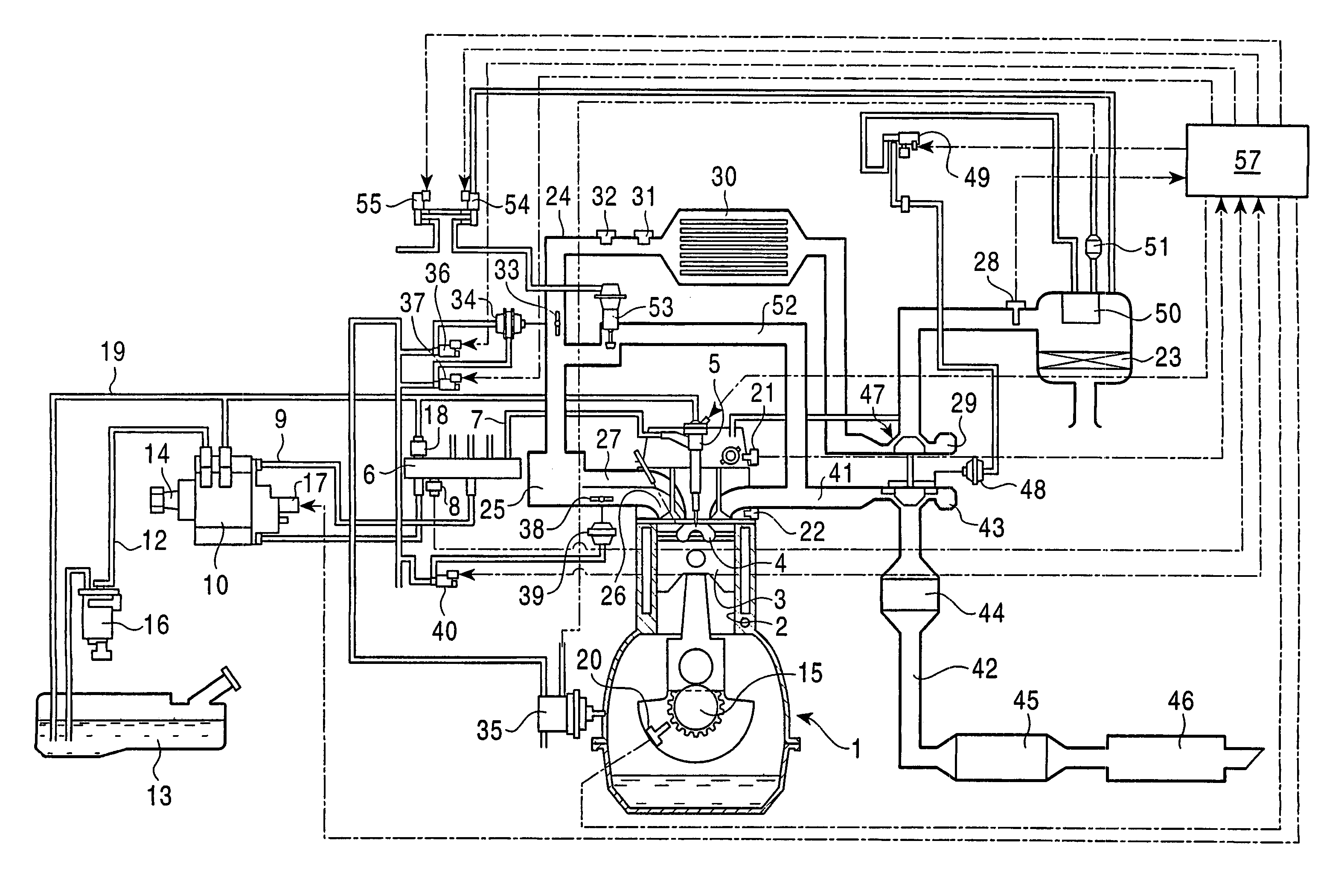
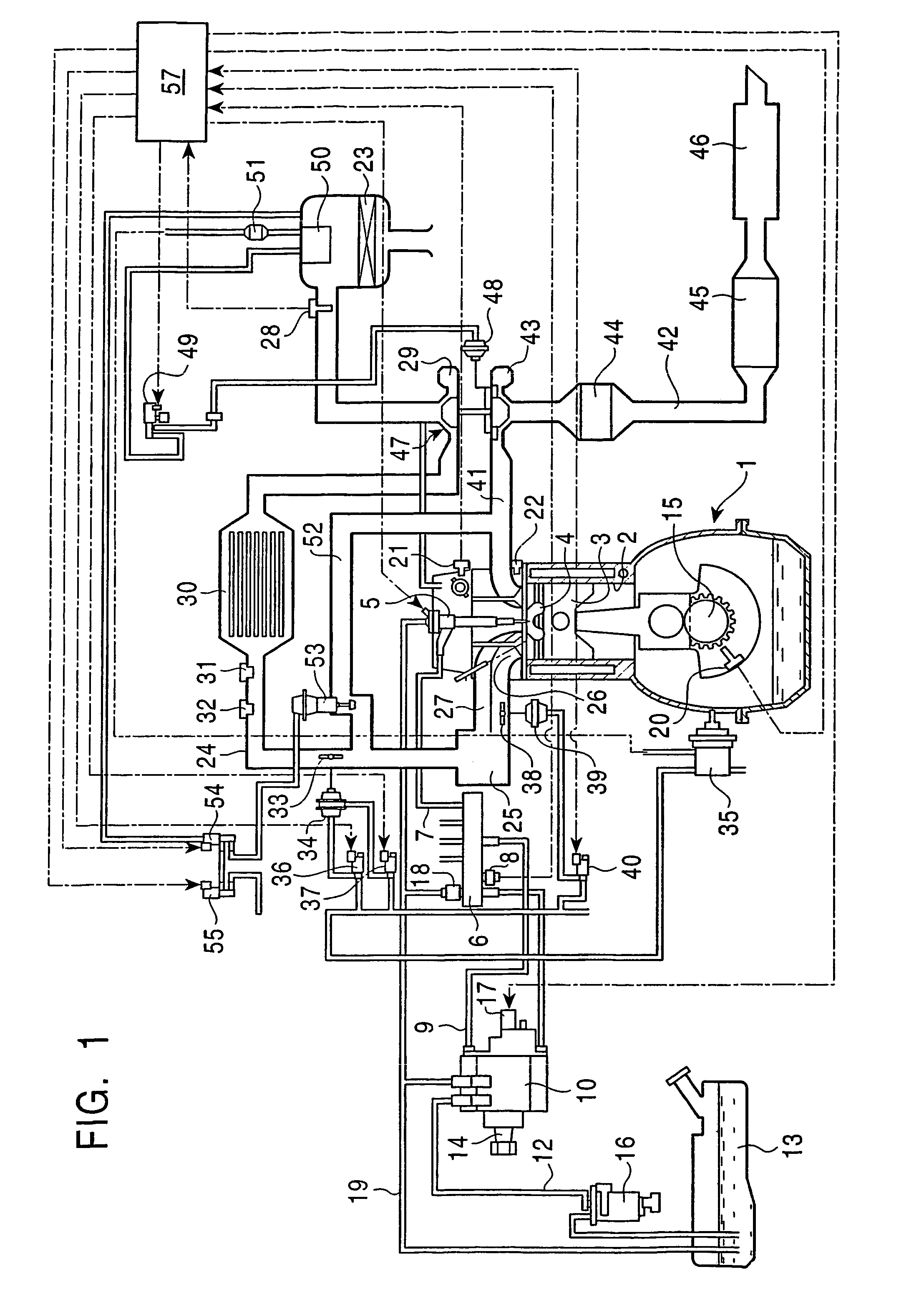
[0038]FIG. 1 is a schematic diagram showing the overall configuration of a diesel engine control system that is a first embodiment of the present invention. This embodiment represents an application of the present invention to an in-line, four-cylinder, direct-injection diesel engine mounted in a vehicle.

[0039]In FIG. 1, reference numeral 1 designates a main engine unit controlled by the control system of this embodiment. The main engine unit 1 is equipped with four cylinders 2 aligned perpendicularly to the drawing sheet. A piston 3 is installed in each cylinder 2 to be reciprocally movable therein. The top face of each piston 3 is formed with a recess 4 forming part of a combustion chamber. A solenoid-type injector (fuel injection valve) 5 is installed at the top center of each cylinder 2 for directly injecting fuel into the cylinder.

[0040]The injectors 5 are connected to a common rail 6 through branch pipes 7. The common rail 6 stores fuel at a higher pressure than the opening pr...

second embodiment

[0079]The control system according to the second embodiment detects the lower limit value of pilot injection (the current supply period at the misfire limit) by the misfire detection method and conducts engine control based on the detected value. The basic configuration of the engine control system of the second embodiment is the same as that of the first embodiment.

[0080]The correction control is conducted by establishing a condition under which the engine misfires if pilot injection is not effected, deliberately creating a misfire state by changing the current supply period for the pilot injection, defining the current supply period at the time misfire was detected (the misfire limit) as the minimum current supply period for pilot injection, and correcting the map for pilot injection.

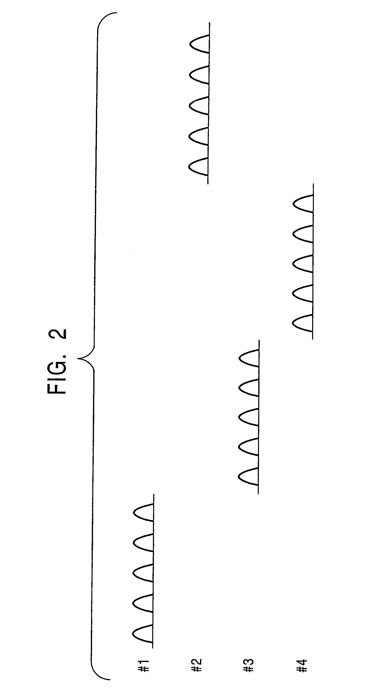
[0081]Specifically, idling operation is first established by, as exemplified in FIG. 8, conducting fuel injection composed of pilot injection and main injection at each cylinder. Next, the injection t...


PUM


Abstract

A diesel engine control system and control method capable of conducting accurate fuel injection unaffected by variations in injector performance caused by differences among individual injectors or change with aging. The diesel engine control system includes an injector for directly injecting fuel into a combustion chamber of a diesel engine, injection quantity controller for controlling fuel injection quantity by varying a period of electric current supply to the injector, estimator for estimating that an electric current supply period when a prescribed (stable) combustion state is obtained is the current supply period for injecting the amount of fuel required for the prescribed combustion state, and control data correcting device for correcting control data of the injection quantity controller based on the estimated current supply period.

Description

[0001]This application is a Continuation of International Application No. PCT / JP02 / 06935, filed Jul. 9, 2002. (status, pending).TECHNICAL FIELD[0002]The present invention relates to a control system and a control method for a diesel engine, particularly to a control system and a control method enabling accurate injection of small quantities of fuel in a diesel engine.BACKGROUND ART[0003]In a diesel engine, the fuel injection quantity is controlled by varying the time period of electric current supply to one or more fuel injectors so as to vary the fuel injection time period. Accurate fuel injection is difficult, however, because the relationship between current supply period and fuel injection quantity differs between different injectors owing to differences in the performance of individual injectors, change with aging and the like. This difficulty is particularly pronounced in the low-load, low-rpm region where the injection quantity per injection is small and in split fuel injecti...

Claims


Application Information

Patent Timeline
Patent Type & Authority Patents(United States)
IPC IPC(8): F02D41/14F02D41/00F02D41/40F02D41/24F02D41/20F02B3/00F02B3/06F02D45/00F02D41/38
CPCF02D41/1498F02D41/2438F02D41/2467F02D41/402F02B3/06F02D41/20F02D41/2441F02D2200/1015Y02T10/44Y02T10/40
Inventor NAKAI, EIJIOKADA, NAOKISATO, TSUNEHIROMATSUMOTO, YOSHIYUKINAKAO, MASAMISAHARA, MASANORIHABU, KOUJISUGANO, HIROMUYAMAMOTO, MASARUMORI, TUNEHIRO
Owner MAZDA MOTOR CORP
Why Eureka
Try Eureka