
Rotary seal for directional drilling tools

a directional drilling and sealing technology, applied in the direction of turning apparatuses, engine components, valve arrangements, etc., can solve the problems of tool failure, valves have been known to stick, valve assembly actuation,

Inactive Publication Date: 2005-11-08
SCHLUMBERGER WCP
View PDF56 Cites 44 Cited by
  • Summary
  • Abstract
  • Description
  • Claims
  • Application Information

AI Technical Summary

Benefits of technology

[0012]The interconnected voids allow fluid pressure to equalize between the sealing faces by allowing flow through the interconnecting voids to the sealing surfaces. Because the fit of the sealing surfaces of the valve is less than perfect, and because the voids on mating surfaces do not necessarily overlap, the 5% of the surface area comprising interconnected voids can easily translate to a 10% or more reduction in sealed area when both sealing surfaces have the interconnecting voids. This additional 10% total reduction in surface area subjected to differential pressure has substantially eliminated the hydraulic lock problem encountered upon startup.

Problems solved by technology

In operation, however, because power to actuate the valve assembly is limited, the valves have been known to stick.
In the past, this condition has caused failure of the tool and an expensive trip of the drill string from the hole.
This patent describes a tribological buildup of the cobalt binder material on the faces of heavily loaded polycrystalline diamond bearing elements, leading to an increase in the operating torque.
However, since the sticking often occurred on initial startup, there was no relative rotation of the valve bodies under load to cause this tribological buildup, so any benefit from this treatment was at best only partially effective.
Another problem with these prior art valve assemblies is that during operation, pressure surges in the drilling fluid can suddenly increase the load on the valve such that the operating torque of the valve exceeds the torque available by the actuator.
An additional problem with these units has been a sudden reverse flow of drilling fluid through the valve assembly caused under conditions when the source of pressurized fluid at the surface has been suddenly stopped or when one or more of the actuators are rapidly forced closed.
This has been known to cause the valve surfaces to become separated.

Method used


Image

  • Rotary seal for directional drilling tools
  • Rotary seal for directional drilling tools
  • Rotary seal for directional drilling tools

Examples


Embodiment Construction

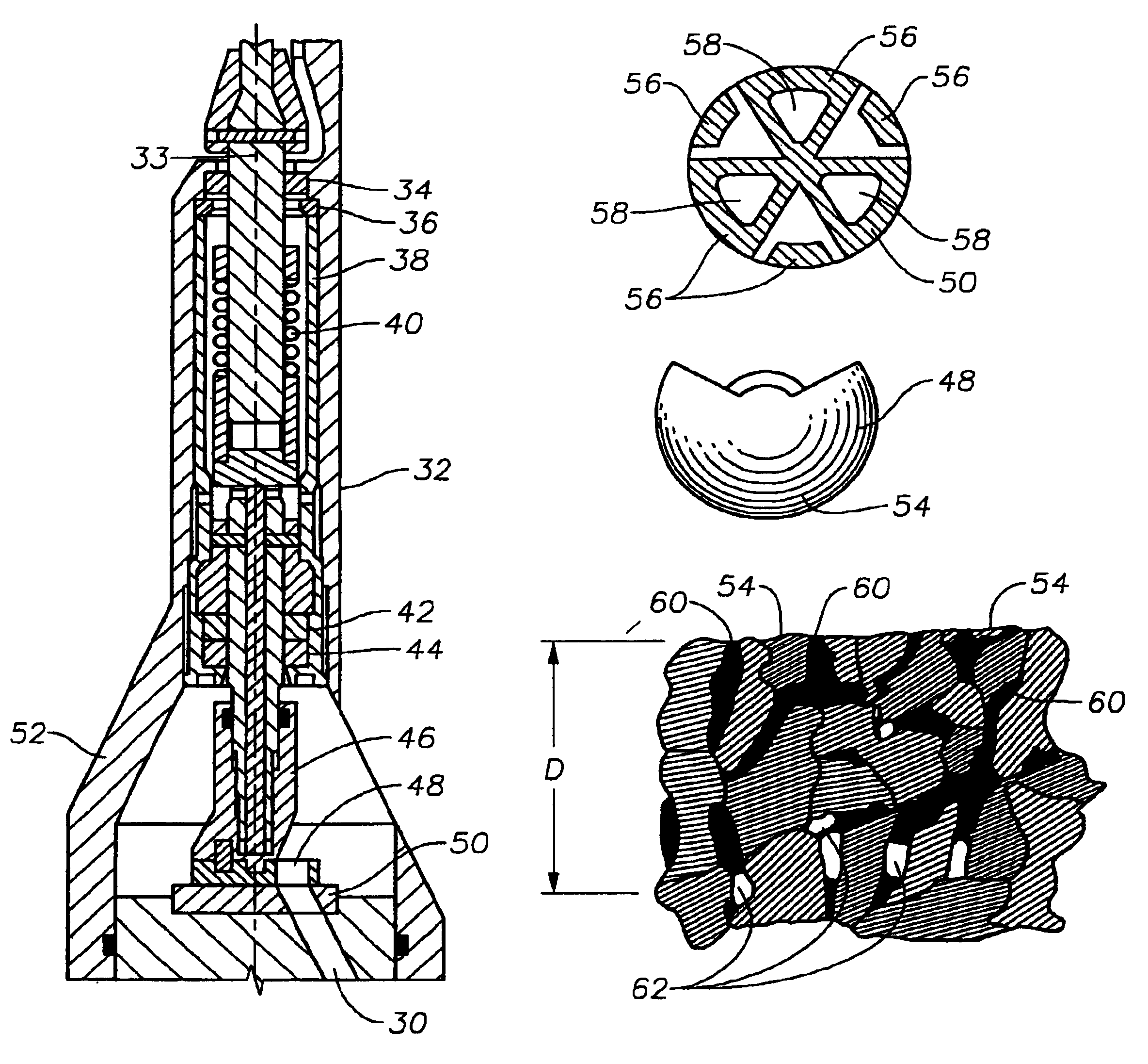
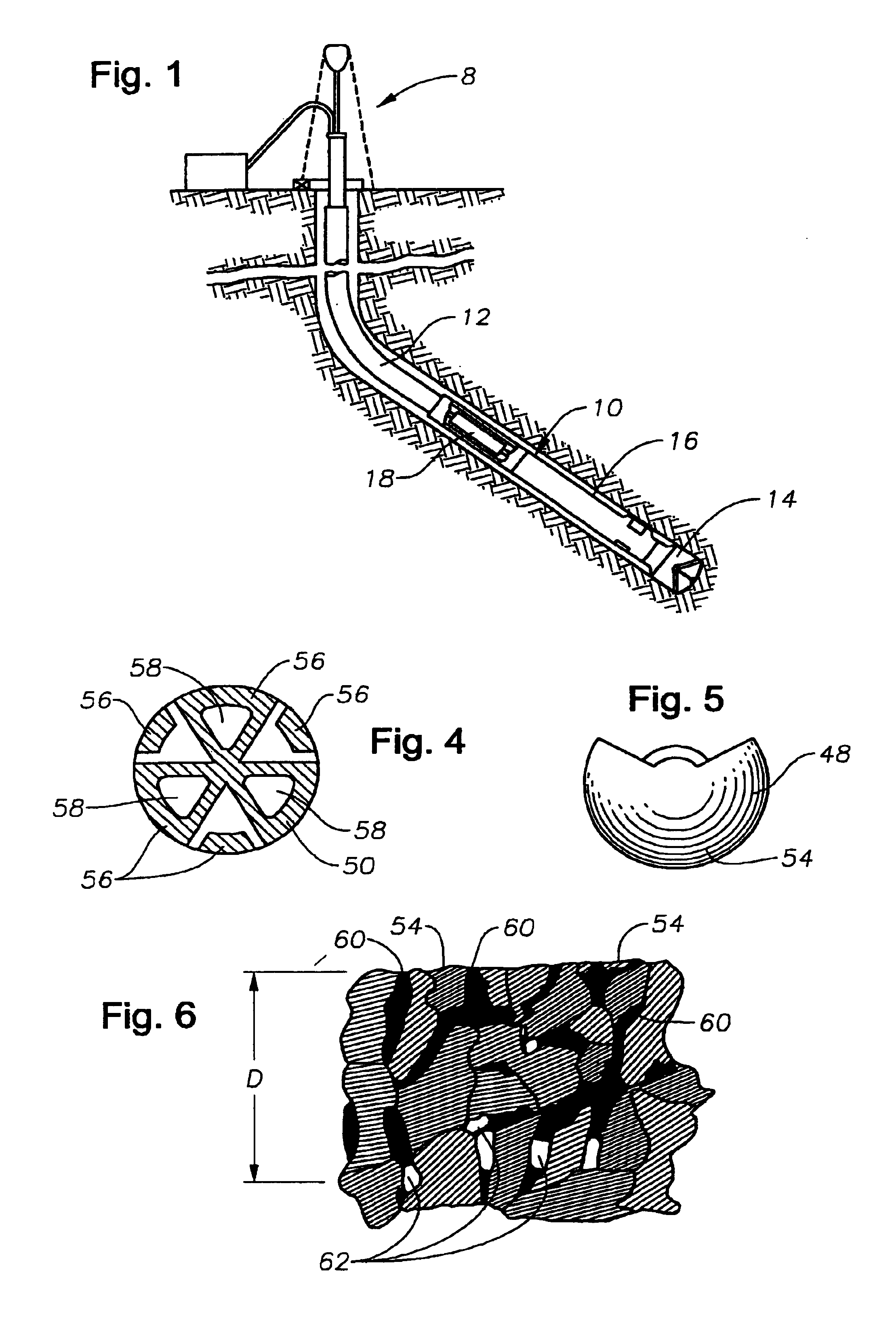
[0021]When drilling directional boreholes into earthen formations, it is common practice to use a bottom hole assembly as shown in FIG. 1. The bottom hole assembly, generally indicated as 10, is typically connected to the end of the tubular drill string 12 which is typically rotatably driven by a drilling rig 8 from the surface. In addition to providing motive force for rotating the drill string 12, the drilling rig 8 also supplies a drilling fluid under pressure through the tubular drill string 12 to the bottom hole assembly 10. The drilling fluid is typically laden with abrasive material, as it is repeatedly re-circulated through the borehole. In order to achieve directional control while drilling, components of the bottom hole assembly 10 include a drill bit 14, a modulated bias unit 16, and a roll stabilized control unit 18. The bias unit 16 is connected to and controlled by the roll stabilized control unit 18, which controls operation of the bias unit 16 in accordance with a pr...


PUM

PropertyMeasurementUnit
Lengthaaaaaaaaaa
Fractionaaaaaaaaaa
Fractionaaaaaaaaaa

Abstract

A rotary valve assembly for a rotary steerable tool is disclosed for directing flow of an abrasive laden drilling fluid; the valve assembly has a first sealing surface rotatably engaging a second sealing surface. At least one of the surfaces has at least about 5% of its area comprising interconnecting voids to an average depth of at least 0.02 mm. The interconnected voids allow fluid pressure to equalize between the sealing faces by flowing through the interconnecting voids to the sealing surfaces. Because the fit of the sealing surfaces of the valve is less than perfect, and because the voids on mating surfaces do not necessarily overlap, the 5% of the surface area comprising interconnected voids can easily translate to a 10% or more reduction in sealed area when both sealing surfaces have the interconnecting voids. The additional reduction in surface area subjected to differential pressure has substantially eliminated the hydraulic lock problem previously encountered upon startup.

Description

CROSS REFERENCE TO RELATED APPLICATIONS[0001]This application claims priority from U.S. Provisional Patent Application Ser. No. 60 / 281,054 incorporated by reference herein by Nigel Griffin and Peter Hughes, filed Apr. 2, 2001, now pending.BACKGROUND OF THE INVENTION[0002]1. Field of the Invention.[0003]This invention relates to a rotary seal for a directional drilling tool, which is useful when drilling boreholes into the earth.[0004]2. Description of the Related Art.[0005]When drilling boreholes into sub-surface formations, it is desirable to be able to vary the direction of drilling. For example to direct the borehole toward a desirable target or to control the direction, a rotary steerable tool may be used in a drill string to change the direction of the borehole. It may also be desirable to correct for deviations from the desired direction when drilling a straight hole. Furthermore, directional drilling tools may also be used to control the direction of the hole to avoid obstacl...

Claims


Application Information

Patent Timeline
IPC IPC(8): B23B27/14B22F7/06C04B37/02C04B41/81C04B35/52C04B41/45C04B41/91C04B41/53E21B7/04E21B7/06E21B7/18E21B21/00E21B21/10F16C33/04E21B10/00E21B10/46E21B10/56E21B10/50E21B10/42E21B10/60E21B10/54E21B7/08E21B10/43E21B10/55E21B10/567E21B10/573
CPCB22F7/06B23B27/145C04B35/52C04B41/459C04B41/53C04B41/81C04B41/91E21B21/10F16C33/04F16K25/005B22F2005/001B22F2998/00B22F2999/00E21B2010/566B22F2207/03B22F1/0014C22C26/00E21B10/5671B22F1/052
Inventor HUGHES, PETER RAYMONDGRIFFIN, NIGEL DENNISCOLEBROOK, MARK A.
Owner SCHLUMBERGER WCP
Features
  • Generate Ideas
  • Intellectual Property
  • Life Sciences
  • Materials
  • Tech Scout
  • Unparalleled Data Quality
  • Higher Quality Content
  • 60% Fewer Hallucinations
Learn More