
Single access dialysis needle

a dialysis needle and single-access technology, applied in the field of extracorporeal hemodialysis, can solve the problems of reducing the life of patients, affecting the treatment of patients, so as to reduce the trauma and tissue damage of patients, prevent blood from returning, and reduce the effect of recirculation

Inactive Publication Date: 2005-11-08
YALE UNIVERSITY CORP
View PDF26 Cites 33 Cited by
  • Summary
  • Abstract
  • Description
  • Claims
  • Application Information

AI Technical Summary

Benefits of technology

"The present invention provides an improved method and apparatus for extracorporeal hemodialysis using a single venipuncture for each treatment. The invention also includes a single access dialysis needle with two lumens and a barrier, which allows for single venipuncture use for both homodialysis and extracorporeal hemodialysis. These technical effects provide greater efficiency and convenience for patients and healthcare professionals."

Problems solved by technology

Many kinds of kidney diseases interfere with the function of the kidney such that the kidney ceases to remove waste and excess water from the blood.
When the kidney is sufficiently impaired that large portions of the waste products and water are not removed from the blood, the life of the patient cannot be preserved unless a way is provided for artificially performing the function of the impaired kidney.
The aforementioned procedure has been found to have serious disadvantages both to the patient and to the attending physicians, nurses, and technicians.
Tissue repeatedly subjected to the trauma of venipuncture is much more susceptible to thrombophlebitis, paravascular hemorrhage, clotting and infection.
In fact, it is commonly found in patients who have experienced a number of venipunctures, that the tissues surrounding the most accessible veins develop large hematomas which obscure the veins, making successful venipuncture extremely difficult because of insufficient blood flow in the damaged blood vessels.
Also contributing to the problem is the fact that once one successful venipuncture is made and blood is allowed to flow from the patient's body toward a hemodialyzer, the blood volume in the patient's body is reduced, making the second venipuncture very difficult.
In addition, while the pain and discomfort suffered by a hemodialysis patient is understandable, the multiple attempts at venipuncture often necessary to place the second needle result in increasing apprehension, and anxiety on the part of both the patient and the physician, nurse, or technician attending the patient further reduces the likelihood of successful venipuncture.

Method used


Image

  • Single access dialysis needle
  • Single access dialysis needle
  • Single access dialysis needle

Examples


Embodiment Construction

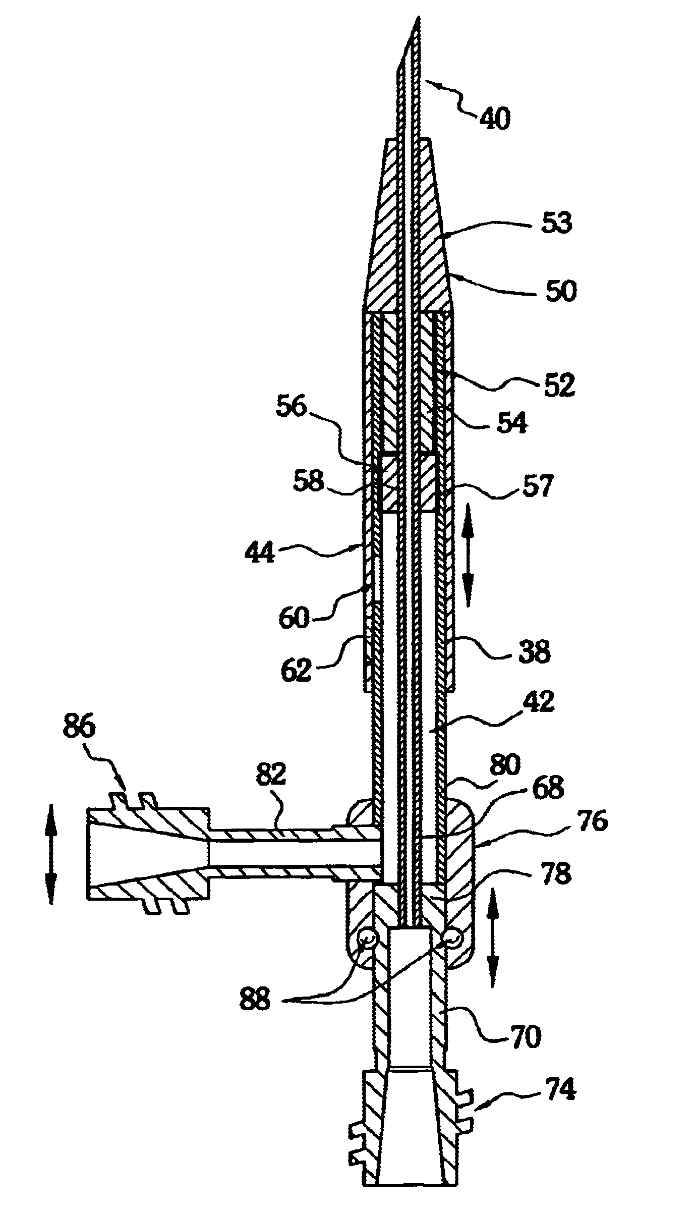
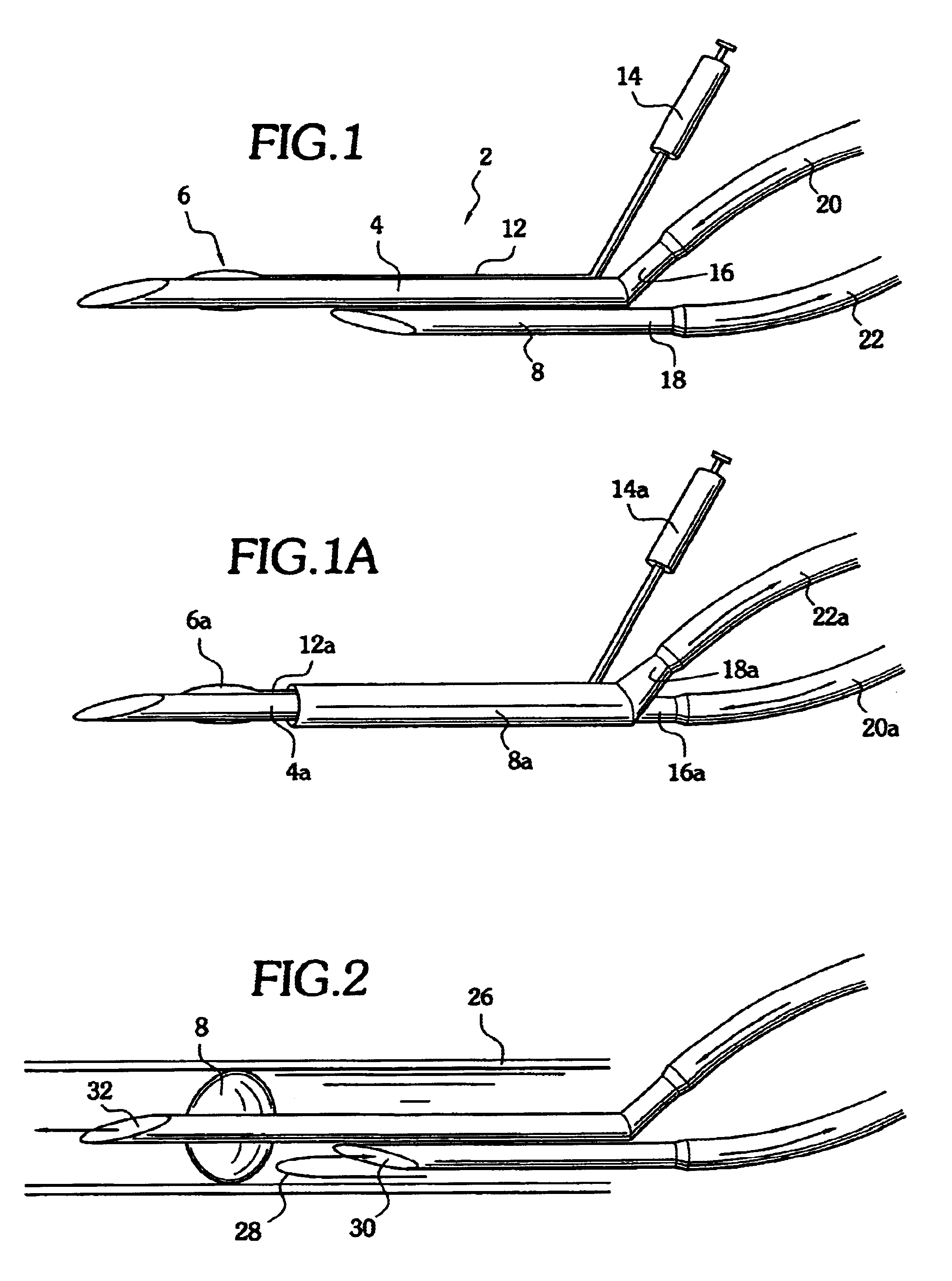
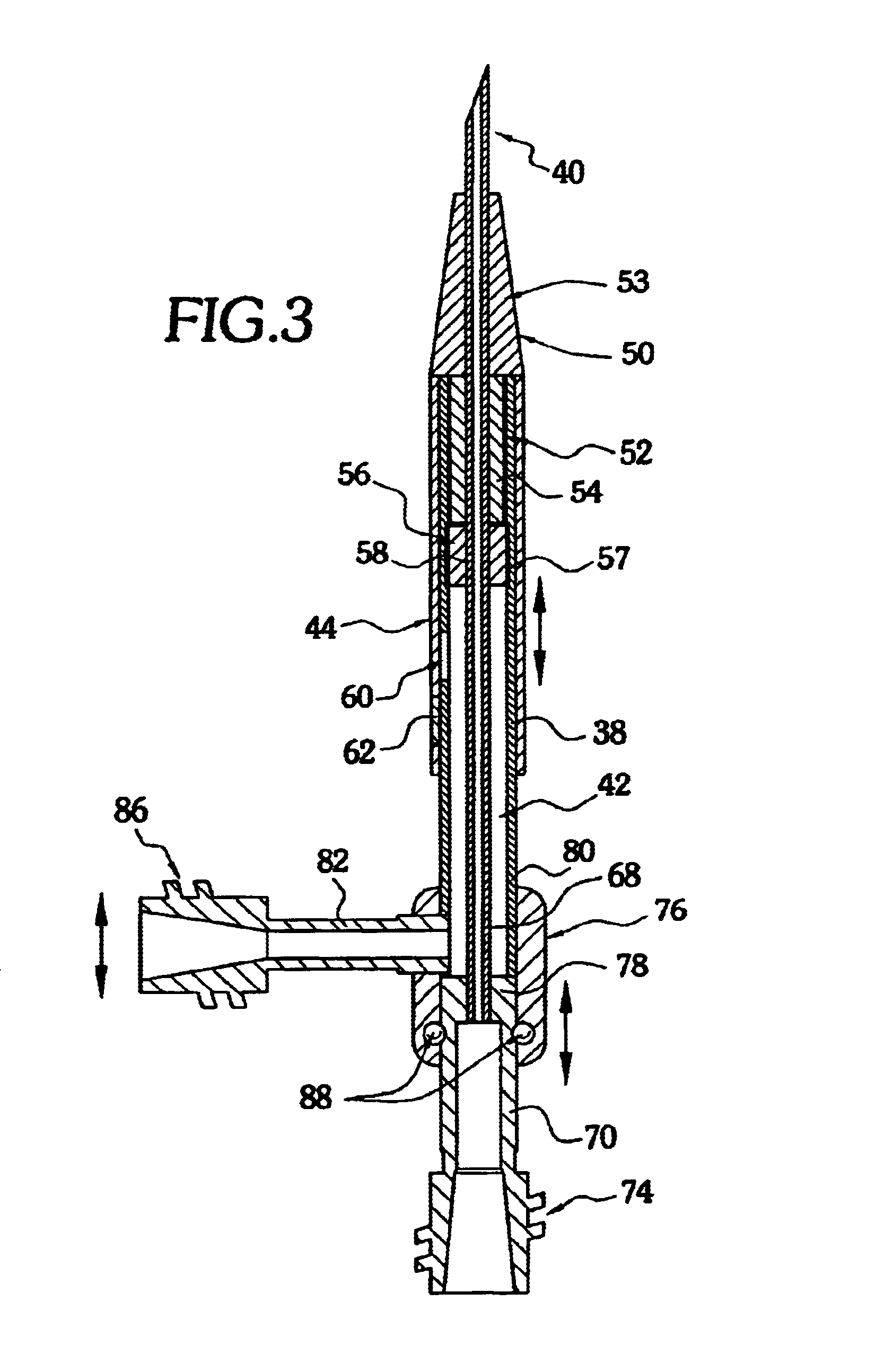
[0020]The invention can perhaps be better understood from the drawings. In FIG. 1 a dialysis needle system 2 comprises a first cannula 4 with an annular balloon 6 and a second cannula 8. Balloon 6 is in fluid communication with an inflation lumen 12 and an inflator 14. Balloon 6 is deployed after insertion of the cannula and positioning within a dialysis fistula. The proximal end 16 of first cannula 4 and the proximal end 18 of second cannula 8 are separated or otherwise configured so that each of proximal ends 16 and 18 can be attached to hoses 20, 22 attached to a hemodialyzer (not shown). First cannula 4 and second cannula 8 are shown in FIG. 1 to be essentially parallel. It should be noted that it is within the scope of the invention that first cannula 4 and second cannula 8 can be coaxial to one another. For example, as shown in FIG. 1A, second cannula 8a circumferentially surrounds first cannula 4a. Balloon 6a is in fluid communication with an inflation lumen 12a and an inflat...


PUM


Abstract

A single access dialysis needle system comprises a first cannula, a second cannula or sheath, and a barrier arranged on the outer surface of the first cannula. The distal end of the first cannula extends distal to the distal end of the second cannula or outer sheath, and the barrier is positioned between the respective distal ends. When the barrier is inflated or otherwise activated, it prevents or minimizes recirculation.

Description

CROSS-REFERENCE TO RELATED APPLICATION[0001]This application is based upon now abandoned U.S. provisional patent application Ser. No. 60 / 354,467, filed Feb. 5, 2002, incorporated herein by reference.FIELD OF THE INVENTION[0002]The invention relates to extracorporeal hemodialysis. More particularly, the invention related to a method and apparatus for dialyzing a patient's blood with a single venipuncture or cannulation.BACKGROUND OF THE INVENTION[0003]Historically, kidney diseases have been of critical concern to human life. Many kinds of kidney diseases interfere with the function of the kidney such that the kidney ceases to remove waste and excess water from the blood. When the kidney is sufficiently impaired that large portions of the waste products and water are not removed from the blood, the life of the patient cannot be preserved unless a way is provided for artificially performing the function of the impaired kidney. Even today, the same general procedure is used for dialyzin...

Claims


Application Information

Patent Timeline
Patent Type & Authority Patents(United States)
IPC IPC(8): A61M29/00A61M3/00A61MA61M1/36A61M25/04A61M25/06
CPCA61M1/3653A61M25/04A61M25/0606A61M2025/0031A61M2025/0037A61M2025/0039A61M2025/1052A61M1/3659A61M1/3661
Inventor TAL, MICHAEL
Owner YALE UNIVERSITY CORP
Learn More