Dual band sleeve antenna

a dual-band antenna and sleeve technology, applied in the direction of resonant antennas, elongated active elements, antenna supports/mountings, etc., can solve the problems of increased cost and manufacturing tolerance requirements, difficult to provide a single antenna solution with acceptable dual-band performance, and difficult to tune the resulting antenna to dual-bands that are not harmonically related

Active Publication Date: 2005-11-08
PCTEL ANTENNA PRODS GROUP
View PDF16 Cites 38 Cited by
  • Summary
  • Abstract
  • Description
  • Claims
  • Application Information

AI Technical Summary

Benefits of technology

[0022]Theoretical models and test data for a first embodiment modeled for dual Wi-Fi frequency bands of approximately 2.4 and 5.5 MHz is shown in FIGS. 3a, 3b, and 4. Selected dimensions of the antenna 1 for the embodiment shown are as follows: antenna element 2: 29 mm long, 1.6 mm diameter sleeve 8: 15.5 mm long, 7.2 mm diameter-dielectric spacer 6: 0.02″ thick, dielectric constant=3.38 As shown by the electrical models and resulting test data, the antenna 1 configuration provides uniform radiation patterns and standing wave ratio performance of less than 1.7 across two non-harmonically related frequency bands. Further, the antenna has a greatly simplified mechanical structure that is cost effective to manufacture from standard, commonly available materials with minimal machining and or metal forming requirements.
[0024]The antenna has been demonstrated with respect to dual Wi-Fi frequency bands. Alternatively, the antenna dimensions may be designed for different target frequency bands. The antenna element dimensions and spacing being appropriately adjusted to match the midpoint frequencies of the chosen target frequency bands for the best overall performance.

Problems solved by technology

Because the standardized “Wi-Fi” protocols are not allocated to frequency bands that are harmonically related to each other, it has been difficult to provide a cost effective single antenna solution with acceptable dual band performance.
Because the choke and the extending antenna element are both ¼ wavelength of the target frequency, it is difficult to tune the resulting antenna to dual bands that are not harmonically related.
However, these configurations have increased cost and manufacturing tolerance requirements.

Method used


Image

  • Dual band sleeve antenna
  • Dual band sleeve antenna
  • Dual band sleeve antenna

Examples


Embodiment Construction

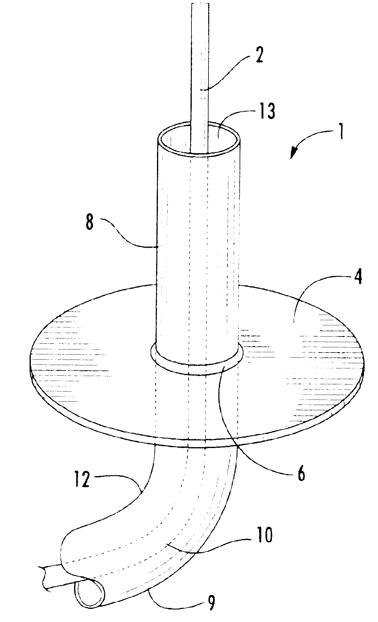
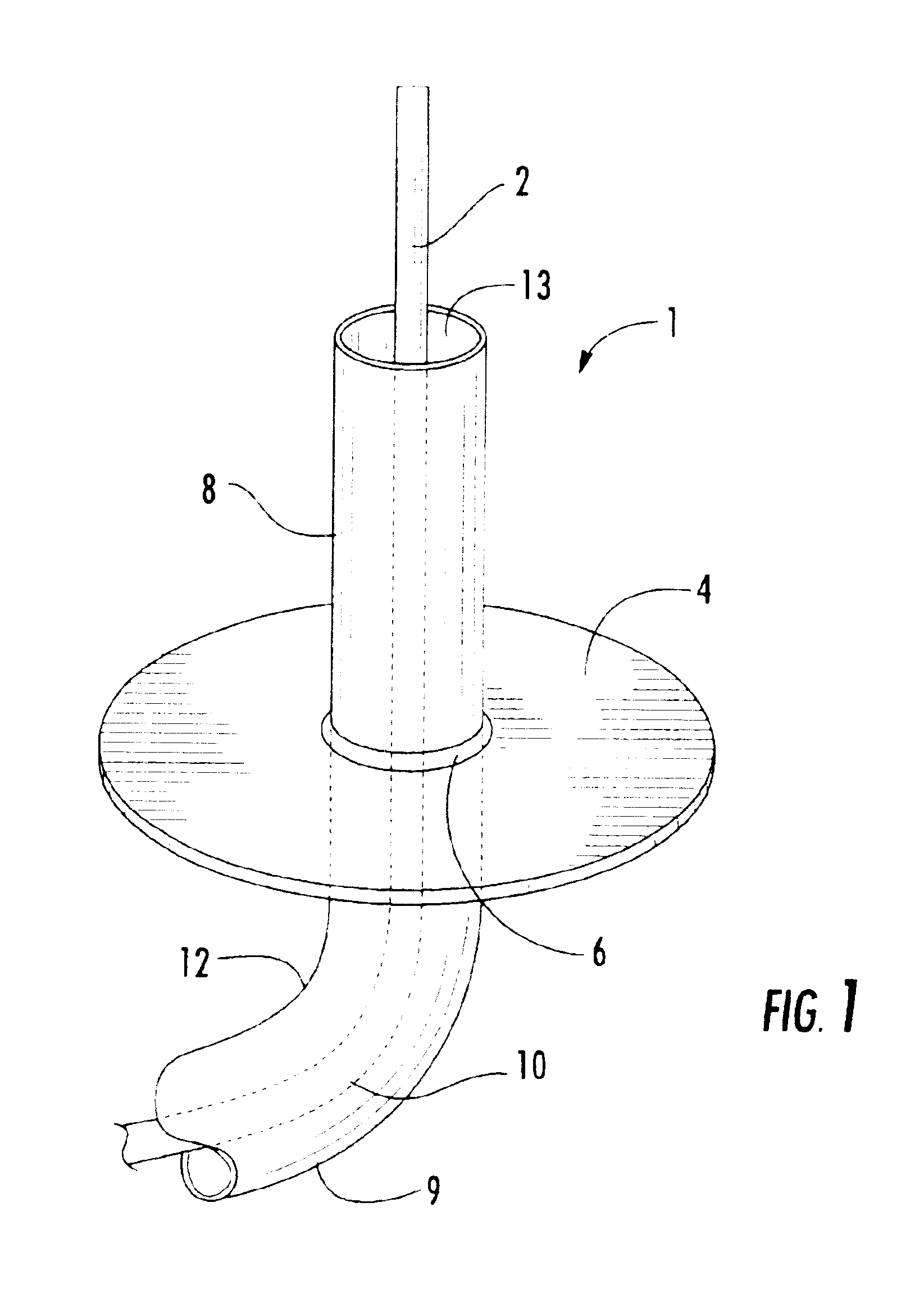
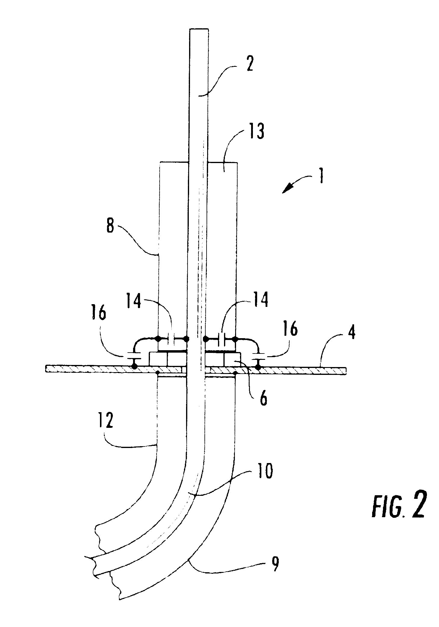
[0016]A first embodiment of the antenna 1 is shown in FIG. 1. An antenna element 2 is fed through an aperture in a ground plane 4 upon which, insulated by a dielectric spacer 6 a sleeve 8 is supported generally concentric about the antenna element 2. The antenna 1 may be fed, for example, by a coaxial cable 9 having an inner conductor 10 coupled to the antenna element 2 and an outer conductor 12 coupled to the ground plane 4.

[0017]In the preferred embodiment, the sleeve 8 has a simple tubular configuration without annular radiuses or other electrically interconnecting structure previously applied to prior “choke” elements. The sleeve element 8 is electrically insulated by the dielectric spacer 6 from direct contact with the ground plane 4 and by the air gap 13 differential between the outer diameter of the antenna element 2 and the inner diameter of the sleeve 8.

[0018]When fed with an RF signal, the sleeve 8 becomes capacitively coupled both to the ground plane 4 and to the antenna ...


PUM


Abstract

A cost efficient multi-band antenna, for use with non-harmonically related frequency bands, for example dual Wi-Fi frequency bands. An antenna element extends away from a ground plane. A sleeve positioned coaxial about the antenna element is spaced apart from the antenna element and the ground plane. Dimensions, spacing and dielectric constants of the antenna element, sleeve and any dielectric spacers are selected to tune the antenna to the desired frequency bands. Further, the ground plane may be the radiating element of, for example a GPS module or SDAR antenna to create a triple frequency band antenna assembly.

Description

BACKGROUND OF INVENTION[0001]1. Field of the Invention[0002]The invention relates to dual-band antennas. More specifically, in a preferred embodiment, the invention relates to a cost efficient antenna tunable for use with both 802.11a and 802.11b / g “Wi-Fi” frequency bands.[0003]2. Description of Related Art[0004]Digital wireless systems, for example wireless local area computer networks, utilize frequency bands allocated for use by specific communication protocols. To provide users with increased connectivity options, it is desirable to provide multiple protocol capability. Because the standardized “Wi-Fi” protocols are not allocated to frequency bands that are harmonically related to each other, it has been difficult to provide a cost effective single antenna solution with acceptable dual band performance.[0005]Sleeve chokes are a known method for tuning a whip and or dipole antenna. Typically the choke is a ¼ wavelength sleeve a distal end coupled to an outer conductor of a coaxia...

Claims


Application Information

Patent Timeline
Patent Type & Authority Patents(United States)
IPC IPC(8): H01Q5/00H01Q1/22H01Q9/04H01Q9/32H01Q1/24
CPCH01Q1/22H01Q1/2258H01Q1/241H01Q9/04H01Q9/32
Inventor DU, XIN
Owner PCTEL ANTENNA PRODS GROUP
Why Eureka
Try Eureka