Optical position measuring device

a technology of optical position and measuring device, which is applied in the direction of instruments, converting sensor output, and geological measurements to achieve the effect of minimal lens width

Inactive Publication Date: 2005-11-08
DR JOHANNES HEIDENHAIN GMBH
View PDF17 Cites 20 Cited by
  • Summary
  • Abstract
  • Description
  • Claims
  • Application Information

AI Technical Summary

Benefits of technology

[0024]The attainment of the object is based on the recognition that, compared with individual lenses, lens arrays, and in particular the linear, periodic arrangement of identical lenses in a defined pattern, have the advantage of short focal length and low structural size, simultaneously along with large illuminated areas in connection with the optical image.

Problems solved by technology

In connecting with the imaging of grating structures by lens arrays the problem arises, that each lens or micro-lens generates a local image, so that phase shifts between the images of the grating structures can occur at the image borders during the transition to the adjoining lens.

Method used


Image

  • Optical position measuring device
  • Optical position measuring device
  • Optical position measuring device

Examples


Embodiment Construction

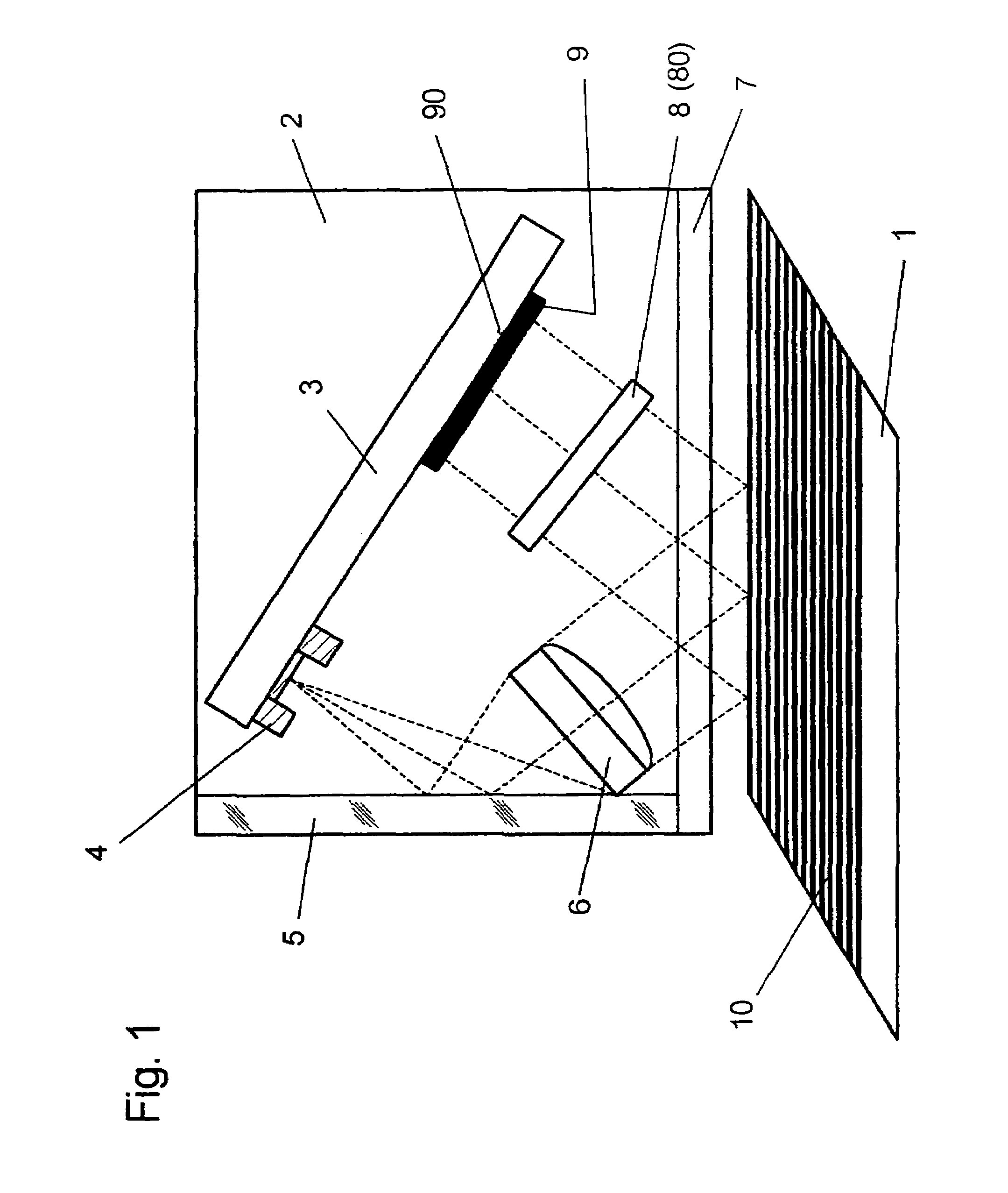
[0075]In a schematic representation, FIG. 1 shows, as parts of an optical measuring system operating in accordance with the incident light measuring method, a scale 1 with a scale grating 10 extending transversely with respect to the scanning direction, and a scanning unit 2, which is movable in relation to the scale 1. The scale grating 10 includes a linear periodic grating which, in the exemplary embodiment in accordance with FIG. 1, is represented as the incremental track of a linear position measuring system. Alternatively, the grating arranged on the scale 1 can be put together from an incremental grating and a grating having a preset graduation period and providing absolute position values.

[0076]The scanning unit 2 contains a printed circuit board 3, which is arranged at a preset angle with respect to the plane of the scale 1 in a scanning housing. A light source 4 in the form of a light-emitting diode and, at a distance from the light source 4, a photoelectric detector 9, whi...


PUM


Abstract

An optical position measuring system including a periodic grating structure and a scanning unit. The scanning unit includes a light source that directs light towards the periodic grating structure and an optical lens device that receives light from the periodic grating structure and creates an image of the periodic grating structure in an image plane, the optical lens device having a periodic lens array with a grating period, AG(r) or the mutual distance between adjoining lenses of said lens array defined by the equation: AG⁡(r)=β⁡(r)*[t⁡(r)*[k+i+n]+ψ](β⁡(r)+1)whereinAG(r) is the grating pert(r) the period of the periodic grating structure,|β(r)| the absolute amount of the image magnification factor β of the lens arrayΨ a presettable defined phase shiftr the radius of the grating arrangement, wherein inthe case of a linear grating r=∞ and AG,t and |β| are constants,i, k, n ε N, i.e. are natural numbers, including zero.

Description

[0001]Applications claim, under U.S.C. §§ 120 and 365, the benefit of priority of the filing date of Apr. 2, 2003 of a Patent Cooperation Treaty patent application, copy attached, Ser. No. PCT / EP03 / 03421, filed on the aforementioned date, the entire contents of which are incorporated herein by reference, wherein Patent Cooperation Treaty patent application Ser. No. PCT / EP03 / 03421 was not published under PCT Article 21(2) in English.[0002]Applicants claim, under 35 U.S.C. § 119, the benefit of priority of the filing date of Apr. 17, 2002 of a German patent application, copy attached, Ser. No. 102 17 726.0, filed on the aforementioned date, the entire contents of which are incorporated herein by reference.BACKGROUND OF THE INVENTION[0003]1. Field of the Invention[0004]The invention relates to an optical position measuring system[0005]2. Description of the Related Art[0006]Optical position measuring systems contain a scanning unit and a scale which is movable relative to the scanning u...

Claims


Application Information

Patent Timeline
Patent Type & Authority Patents(United States)
IPC IPC(8): G01D5/38G01D5/26G01D5/347G02B3/00
CPCG01D5/34715G01D5/38
Inventor BENNER, ULRICHMAYER, ELMAR
Owner DR JOHANNES HEIDENHAIN GMBH
Why Eureka
Try Eureka