
Seismic data processing method to enhance fault and channel display

Active Publication Date: 2005-11-08
SAUDI ARABIAN OIL CO
View PDF6 Cites 2 Cited by
  • Summary
  • Abstract
  • Description
  • Claims
  • Application Information

AI Technical Summary

Benefits of technology

[0011]It is an object of the present invention to provide a method for processing and displaying seismic data from a three-dimensional subsurface volume that avoids the problems of the prior art.
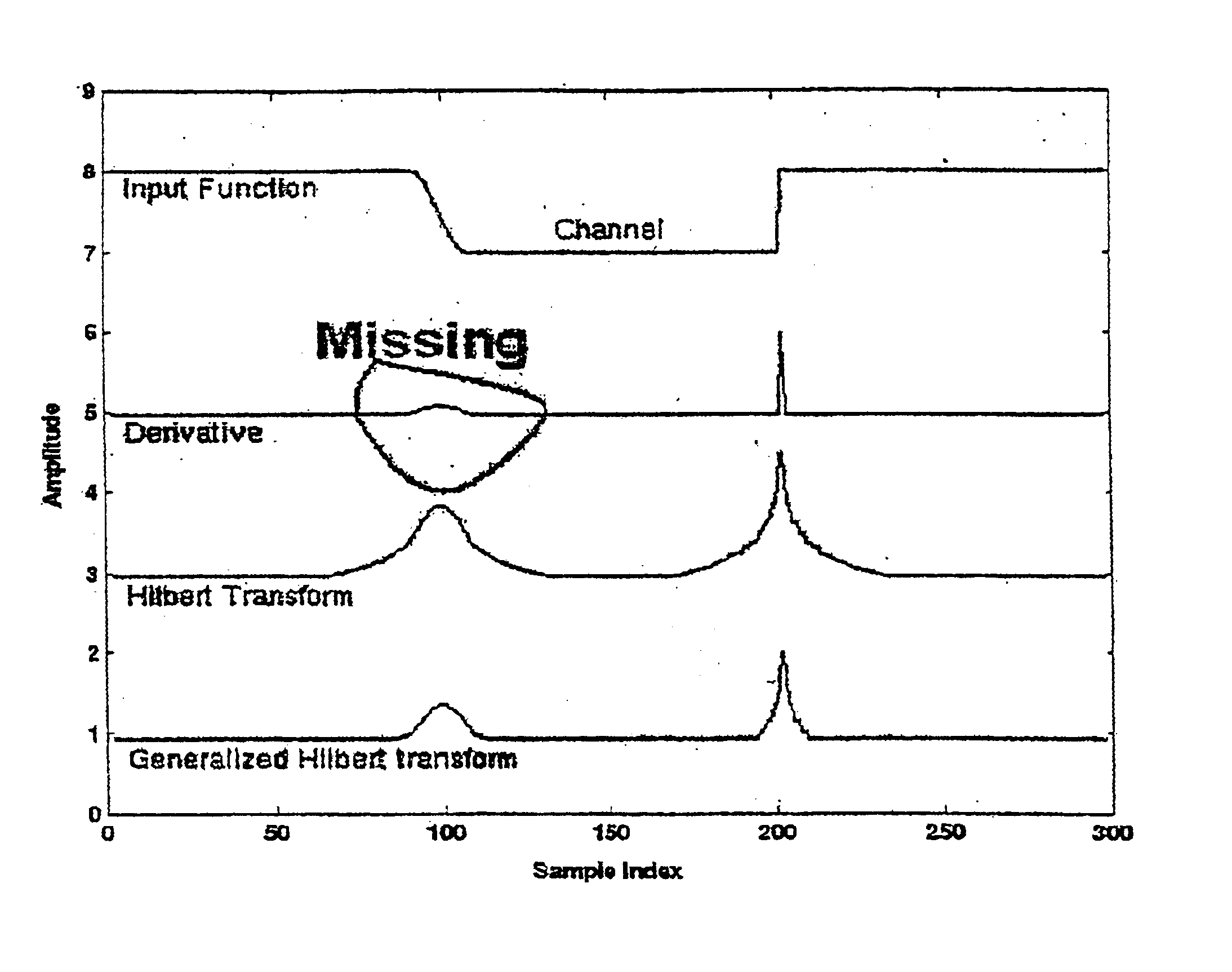
[0013]It is still a further object of the present invention to provide an improved method for processing seismic data that will produce enhanced fault and channel depiction in a three-dimensional display.

Problems solved by technology

The reflected seismic wave energy can be recorded at a number of shotpoints, resulting in similar artifacts on a number of adjacent seismic traces.
However, methods applying Hilbert transforms to other than three-dimensional subsurface volumes are not particularly relevant to generating from seismic data an image representing the volume in three dimensions.
However, in many instances these methods result in depictions of structural features such as faults, and stratigraphic features such as facies changes from reservoir quality rock to non-reservoir quality rock, that either lack clarity or simply do not appear in the depiction.
As a result, even a highly trained interpreter may be unable to identify or predict the likely petrophysical characteristics of the three-dimensional subsurface volume under examination.
More specifically, the inadequacy of conventional methods for processing and displaying seismic data shows up particularly in the difficulty they encounter in clearly highlighting possible faults and channels associated with gradual, as compared with rapid or abrupt, changes in the reflected seismic wave fields.
This limitation is due, at least in part, to the fact that currently available detection methods were designed to detect only abrupt local changes in the seismic wave fields, and do not address the detection of gradual changes.

Method used


Image

  • Seismic data processing method to enhance fault and channel display
  • Seismic data processing method to enhance fault and channel display
  • Seismic data processing method to enhance fault and channel display

Examples


Embodiment Construction

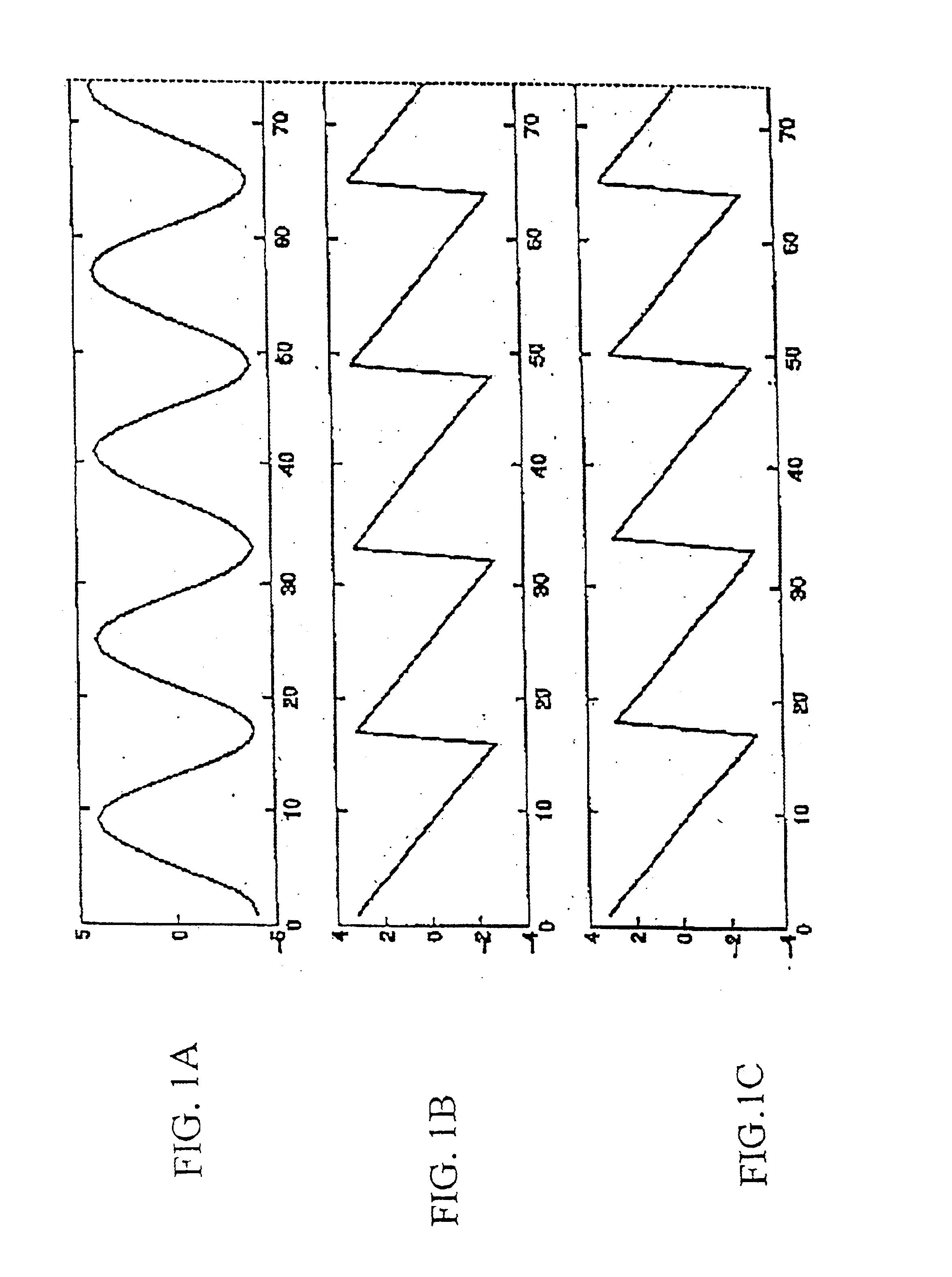
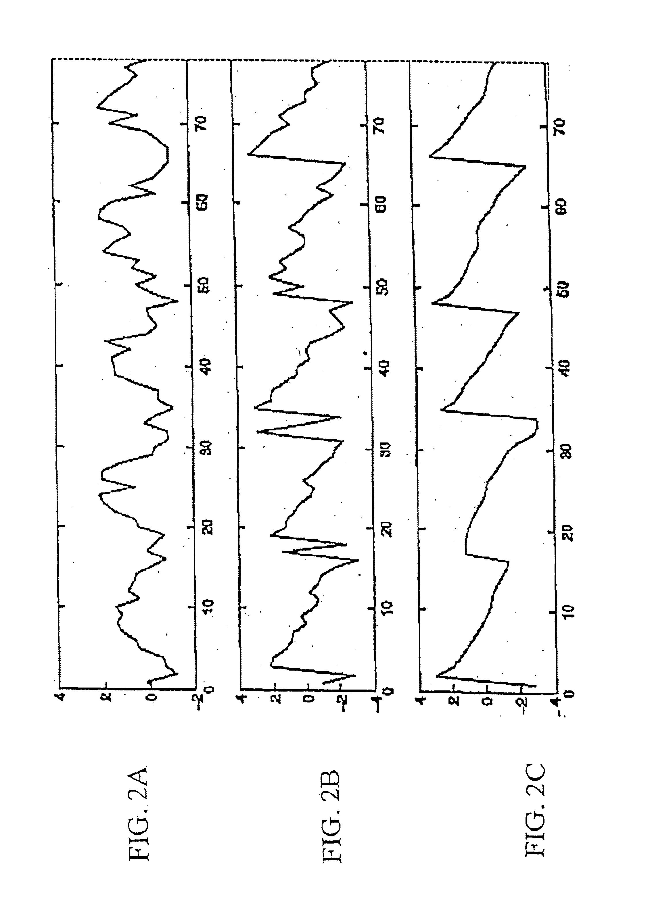
[0039]As indicated above, the present invention involves the use of a Generalized Hilbert Transform, of which the traditional Hilbert transform is a special case. Before describing the preferred embodiments of the present invention, therefore, a description of the traditional Hilbert transform will be given.

[0040]The traditional Hilbert transform (HT) in the frequency domain can be expressed as:

hi(ω)=X(ω)·Sign(ω)·i  (1)

[0041]Here, X(ω) is the Fourier transform of an input trace, Sign(ω) is the sign function and hi(ω) is the Hilbert transform of x(t) in the frequency domain.

[0042]Applying, the inverse Fourier transform to hi(ω) in equation (1) yields:

hi(t)=Σω{X(ω)·Sign(ω)·i·exp(iωt)}  (2)

[0043]For t=0, Equation (2) yields:

hr(0)=2*ΣωReal[X(ω)]+Real[X(0)]  (3)

hi(0)=2*Σω[Image X(ω)]  (4)

h(0)=hr(0)+i*hi(0)  (5)

[0044]where Σω means summation over positive frequencies, and hr and hi are the real and imaginary parts of the complex trace h.

[0045]Equations 3-5 states that hi(t) can be express...


PUM


Abstract

A method of processing data of seismic traces for geophysical interpretation of the earth's subsurface includes the steps of determining a modified Hilbert transform of an input trace of data values to detect rapid and slow changes in the input trace with reduced sensitivity to noise and providing results of modified Hilbert transform to enable identification of any detected rapid or slow changes. The modified Hilbert transform is advantageously a windowed Fourier transform, wherein the input trace is represented as x(t), where t indicates time, a window function is represented by win(τ), a first function is defined as g(τ)=x(t−τ)·win(τ), X(t,ω) is the Fourier transform of g(τ), hi(t) represents a sum over imaginary portions of X(t,ω), hr(t) represents a sum over real portions of X(t,ω), and the modified Hilbert transform is h(t)=hr(t)+i·hi(t). In its most general form, for any integer n greater than 1, hr(t)=ΣωReal {X(t,ω)}n and hi(t)=ΣωImag{X(t,ω)}n.

Description

BACKGROUND OF THE INVENTION[0001]1. Field of the Invention[0002]The present invention relates generally to processing and display of seismic data, and more particularly to processing and display of seismic data using a modified Hilbert transform.[0003]2. Description of Related Art[0004]To find the most likely locations of hydrocarbon deposits beneath the earth's surface, geophysicists use techniques that evaluate and interpret the structure of subsurface formations. The effects of stratigraphy, lithology and pore fluid content on geophysical data, properly interpreted, can be evaluated to predict the likelihood that hydrocarbon deposits are present in the volume under analysis.[0005]Traditionally, subsurface formations are analyzed using seismic reflection data that is processed to image acoustic boundaries in the subsurface. Seismic wave energy projected into the earth reflects in particular ways from subsurface changes in the rock properties or from combinations of such changes. T...

Claims


Application Information

Patent Timeline
IPC IPC(8): G01V1/36G01V1/28
CPCG01V1/364G01V1/28
Inventor LUO, YI
Owner SAUDI ARABIAN OIL CO
Learn More