Mid-sheath cable preparation tool

Inactive Publication Date: 2005-11-15
AMERICAN TELEPHONE & TELEGRAPH CO
View PDF16 Cites 7 Cited by
  • Summary
  • Abstract
  • Description
  • Claims
  • Application Information

AI Technical Summary

Benefits of technology

[0014]The method may also include the steps of clamping a cable stabilization bushing around the cable,

Problems solved by technology

In the installation and maintenance of transmission cable such as fiber optic cable, the removal of poly sheathing frequently presents difficulties in safeguarding the delicate transmission fibers contained within the sheath.
The problem is especially precarious during optical fiber cable work when there is working service on the fiber cable.
In such situations, the cable sheath frequently must be removed at a location distant from the ends of the cable (“mid-sheath

Method used


Image

  • Mid-sheath cable preparation tool
  • Mid-sheath cable preparation tool
  • Mid-sheath cable preparation tool

Examples


Example

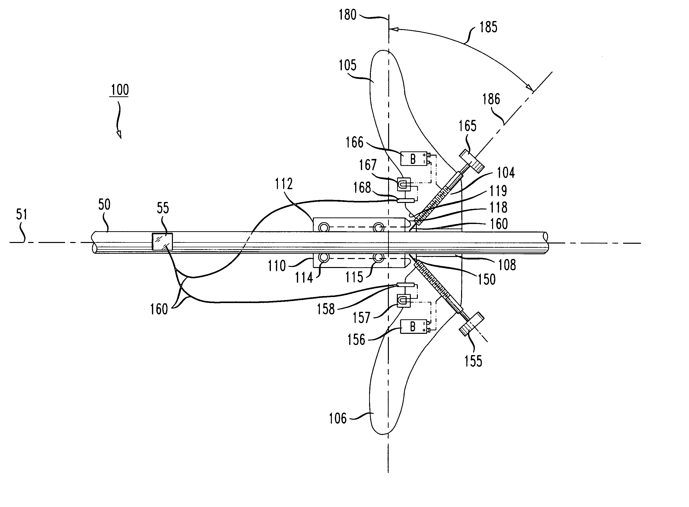
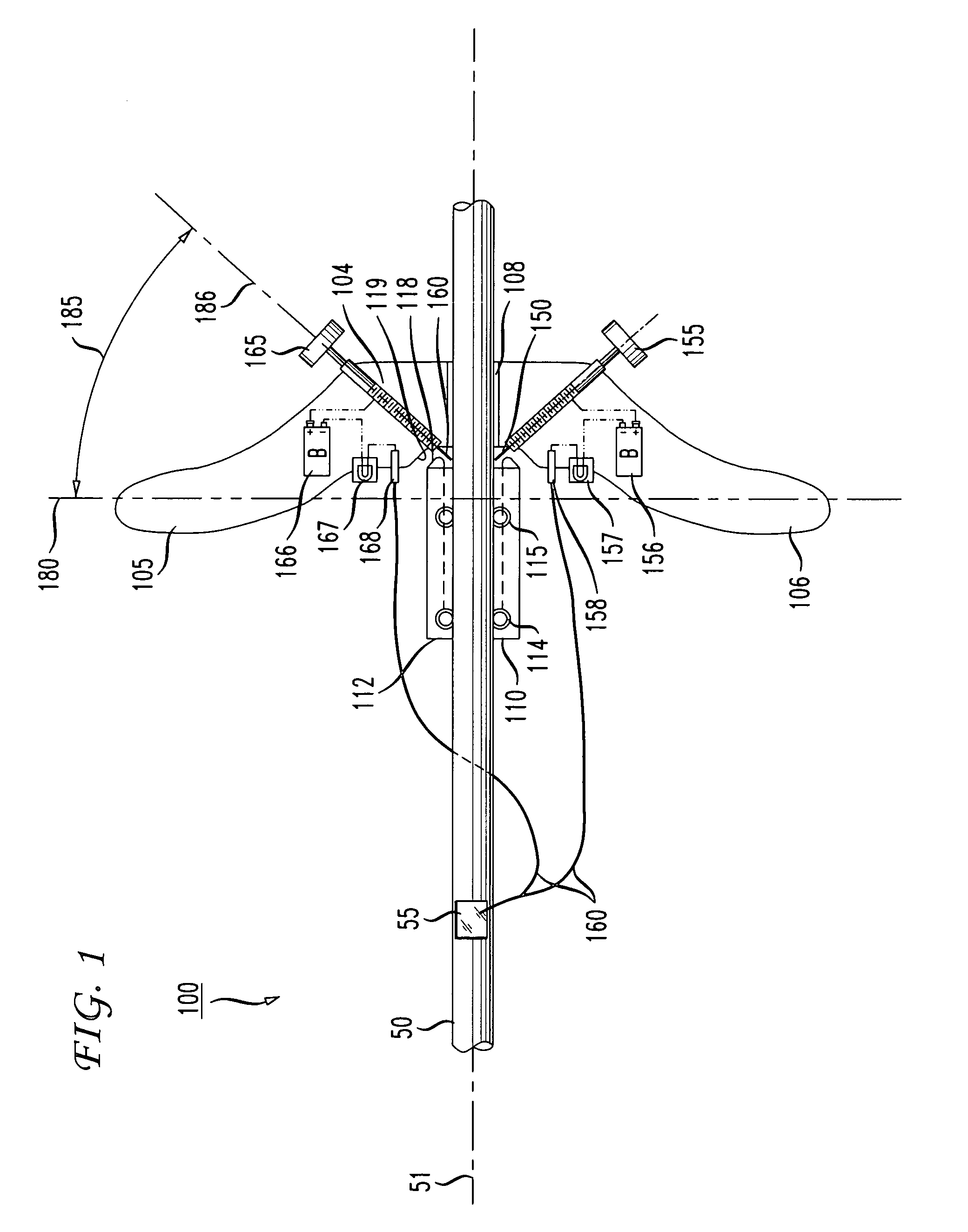
[0026]An apparatus 100 according to the present invention is shown in FIG. 1. The apparatus is for removing polyethylene sheath from a cable 50 in a region between the ends of the cable. The apparatus is generally in the form of a draw knife that can be locked around the fiber cable. The poly sheath is then peeled as the unit is pulled along the cable 50.

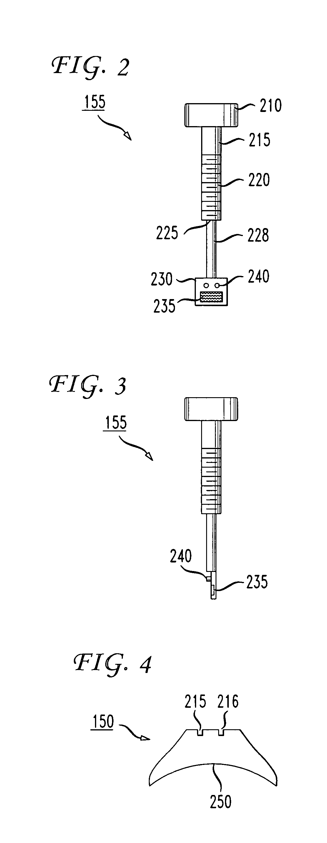
[0027]A dual handle assembly includes a cutter body 104 and two handles 105, 106 for grasping during the cutting stage of the sheath removal process. The cutter body 104 has a central bore 108 for receiving the cable 50 as described below. Disposed within the cutter body 104 are two blade adjustment / retention assemblies 155, 165 for holding the cutting blades 150, 160 in position for cutting and removing the sheath covering cable 50. The blades 150, 160 protrude into the central bore 108. While the apparatus of the invention will be described herein as comprising two blades and two adjustment / retention assemblies, the assembly may c...


PUM

PropertyMeasurementUnit
Angleaaaaaaaaaa
Shapeaaaaaaaaaa
Radiusaaaaaaaaaa

Abstract

The present invention is an apparatus and method for removing a portion of a cable sheath. First and second opposing blades are adjustable to a cutting depth using adjustment screws and continuity testers that signal contact between each blade and a metallic sub-sheath. The blades are inclined at an angle to a transverse plane of the cable, and are contoured to conform to the sheath radius. A guide including neoprene rollers keeps the cutting assembly aligned on the cable. The cutting assembly is drawn along the cable, removing the sheath.

Description

FIELD OF THE INVENTION[0001]The present invention relates generally to the repair of optical fiber cables having a polyethylene or other protective sheath. More particularly, the present invention is an apparatus and method for removing a portion of the poly sheath at a point on the cable remote from the ends.BACKGROUND OF THE INVENTION[0002]In the installation and maintenance of transmission cable such as fiber optic cable, the removal of poly sheathing frequently presents difficulties in safeguarding the delicate transmission fibers contained within the sheath. The problem is especially precarious during optical fiber cable work when there is working service on the fiber cable. In such situations, the cable sheath frequently must be removed at a location distant from the ends of the cable (“mid-sheath”), making the task even more difficult. The industry standard approach to that problem is presently for the OSP technician to use hand-held cutting knives to remove the polyethylene ...

Claims


Application Information

Patent Timeline
IPC IPC(8): G02B6/44
CPCG02B6/4497G02B6/566
Inventor BELEW, MICHAEL SHANEESLAMBOLCHI, HOSSEINHUFFMAN, JOHN SINCLAIR
Owner AMERICAN TELEPHONE & TELEGRAPH CO
Why Eureka
Try Eureka