
Outboard motor

a technology for outboard motors and motors, applied in the field of outboard motors, can solve the problems of large temperature rise, difficult to lighten, and difficult to have the center of gravity disposed at a low position of each disclosed outboard motor, so as to achieve effective and forcible ventilation of the engine compartment, increase engine output, and prevent overheating

Active Publication Date: 2005-11-15
SUZUKI MOTOR CORP
View PDF10 Cites 18 Cited by
  • Summary
  • Abstract
  • Description
  • Claims
  • Application Information

AI Technical Summary

Benefits of technology

[0025]Accordingly, it is an object of the present invention to provide an outboard motor which includes an engine inlet path and an engine compartment that are independently formed to effectively and forcibly ventilate the engine compartment, thereby making it possible to prevent overheating in the engine compartment and maintain the density of combustion air at a sufficient value, so that engine output is increased.
[0026]It is another object of the present invention to provide an outboard motor which, by vigorously ventilating the inside of an engine compartment, makes it possible to effectively prevent overheating of parts in the engine compartment and to stably maintain the operation of the parts in the engine compartment, so that the parts are durable for a longer time and have increased life.
[0027]It is still another object of the present invention to provide an outboard motor which includes a fly-wheel that is short overall, is lightened, has its center of gravity disposed at a low position, and has a large inertia even if it is lightened, and which makes it possible to prevent changes in load in a low-speed rotation region by accommodating variations in rotation of an engine as a result of rotationally balancing and stably rotating the fly-wheel.
[0028]It is still another object of the present invention to provide a compact outboard motor which includes a fly-wheel magneto device that is lightened, that has its center of gravity disposed at a low position, and that provides high electrical power generation output and is designed with greater freedom while reducing the overall height of the fly-wheel magneto device.
[0029]It is still another object of the present invention to provide an outboard motor which includes a fly-wheel that is lightened, has its center of gravity disposed at a low position, and has a large inertia, which makes it possible to smooth out variations in torque each time combustion in an engine occurs on the one hand, and to effectively and efficiently prevent overheating of parts in an engine compartment in order to stably maintain operational functions of the parts in the engine compartment over a long period of time and, thus, to increase their lives on the other.

Problems solved by technology

Therefore, a large temperature rise occurs in the engine compartment c. The large temperature rise may overheat the parts in the engine compartment c.
For this reason, the position of the center of gravity of the fly-wheel k is high, thereby making it difficult for each of the disclosed outboard motors to have its center of gravity disposed at a low position and to be lightened.
Therefore, the fly-wheel becomes heavier.
As a result, it is difficult to make the fly-wheel k light and compact, and the position of the center of gravity of the fly-wheel k is high, thereby hindering stable rotation of the fly-wheel k.
The fly-wheel k, mounted to the protruding portion at the top end of the vertical crank shaft h, is a big factor in determining the overall height and weight of the multi-cylinder engine g. However, since the fly-wheel k is tall overall, it is difficult for each of the disclosed outboard motors to be compact and light and to have its center of gravity disposed at a low position.
Therefore, overheating of the parts in the engine compartment is not sufficiently prevented.
Consequently, for example, the operation of the parts in the engine compartment, such as electrical parts, is impaired, and it is difficult to ensure durability of the parts.
Therefore, the fly-wheel cannot be made lighter and the position of its center of gravity cannot be lowered, as a result of which it is difficult to make the outboard motors compact and light.
The larger the distance to the center of gravity of the fly-wheel from the top-end supporting portion of the crank shaft due to the position of the center of gravity of the fly-wheel being high, there is a greater chance that slight variations in rotational balance of the fly-wheel increase vibration.
Therefore, a load is exerted upon the crank shaft and bearing more than is necessary, thereby increasing vibration of the crank shaft, impairing durability of the crank shaft, and damaging the crank shaft.

Method used


Image

  • Outboard motor
  • Outboard motor
  • Outboard motor

Examples


Embodiment Construction

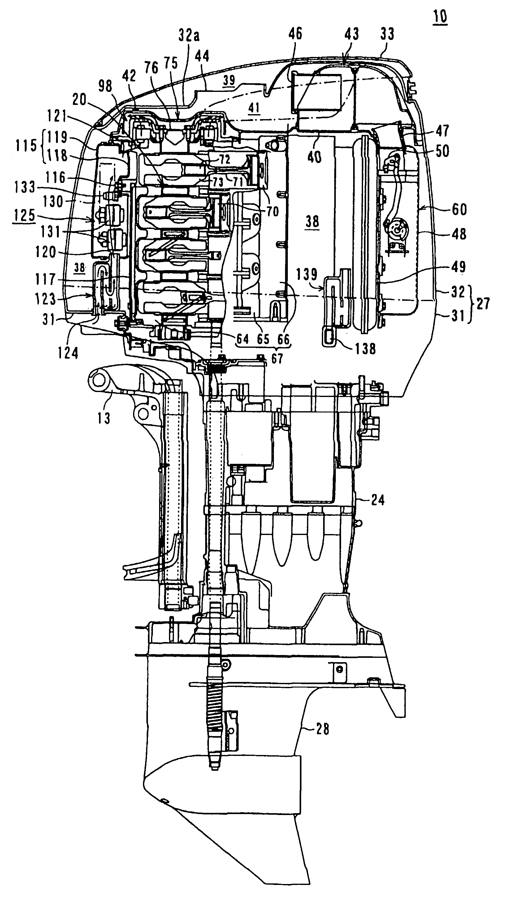
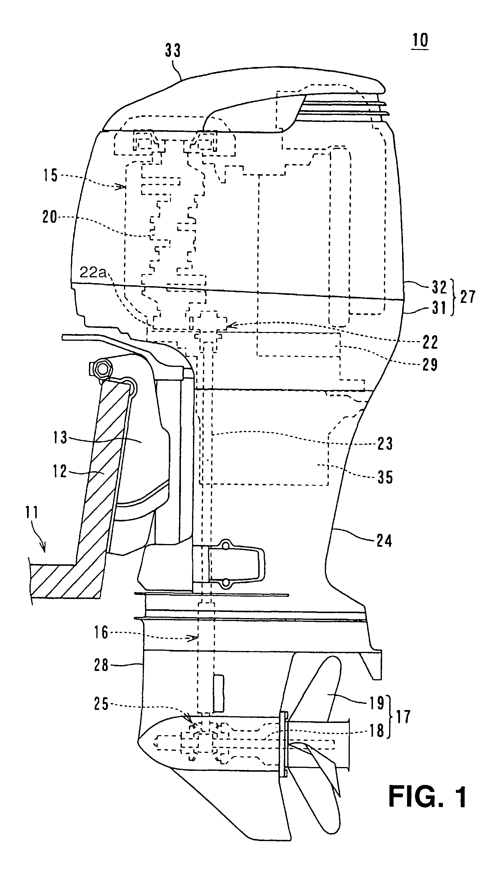
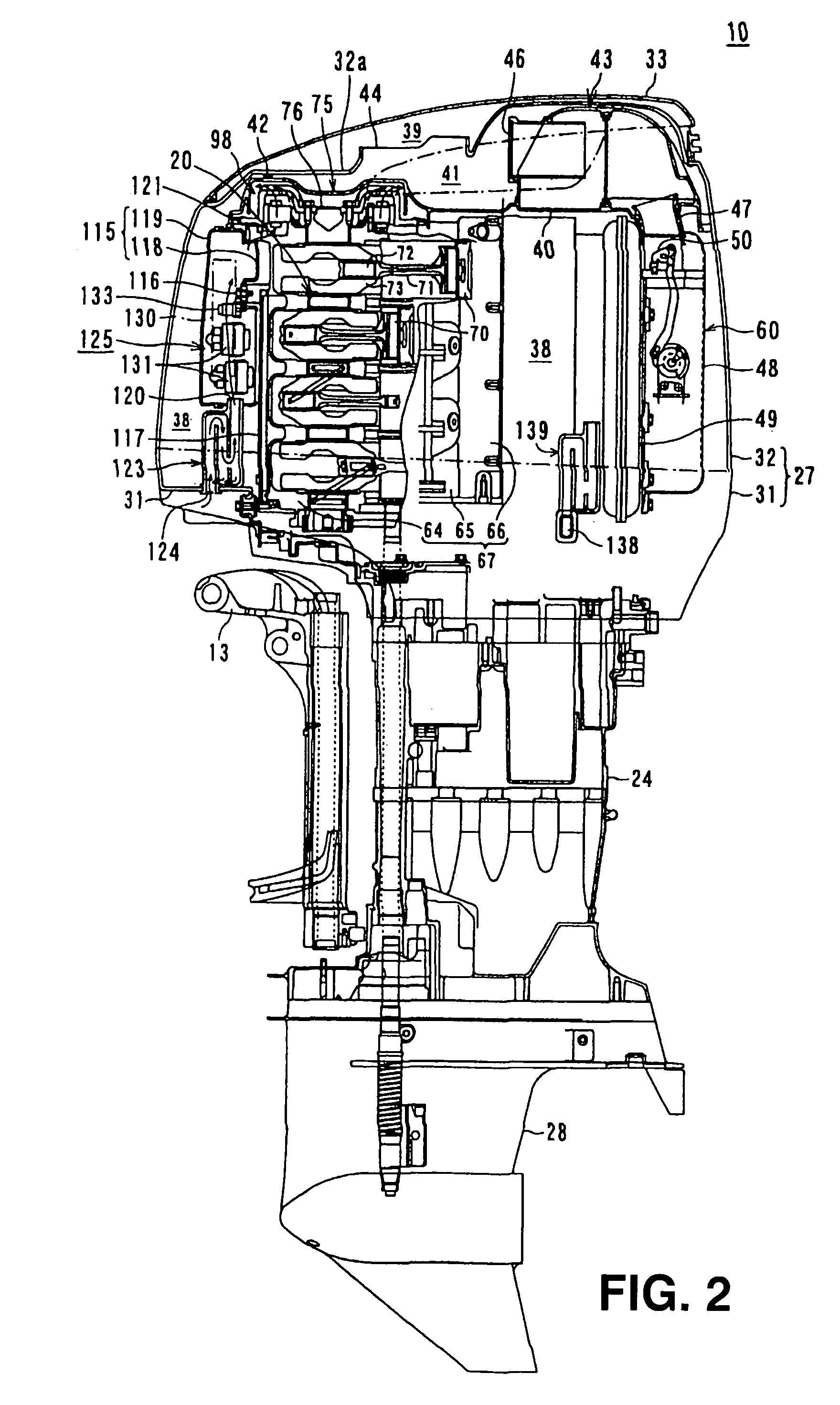
[0061]FIG. 1 is an overall schematic left side view of an outboard motor of an embodiment of the present invention. An outboard motor 10 is mounted to a transom 12 of a hull 11 through a mounting bracket 13 so as to freely face upward and downward. The outboard motor 10 comprises a V-type vertical multi-cylinder engine 15. Output from the V-type multi-cylinder engine 15 is transmitted to a propulsion device 17 through a power transmission device 16. The propulsion device 17 comprises a propeller shaft 18, to which engine output is transmitted, and a propeller 19, which is secured to the propeller shaft 18.

[0062]The V-type multi-cylinder engine 15 is a vertical engine having a vertical crank shaft 20 disposed substantially vertically therein. Engine output from the lower end of the crank shaft 20 is taken out. The lower end of the crank shaft 20 is operationally connected to the upper end of a drive shaft 23 through a primary gear device 22. The drive shaft 23 extends substantially v...


PUM


Abstract

An outboard motor includes a vertical multi-cylinder engine, a fly-wheel magneto device, a partition plate, and a ventilation fan. The vertical multi-cylinder engine is disposed in an engine cover and comprises a crank case and a crank shaft, the crank shaft being rotatably disposed and protruding upward from the crank case. The fly-wheel magneto device is disposed on the protruding portion of the crank shaft. The partition plate is disposed in the engine cover and partitions the inside of the engine cover into an engine air-inlet space and a space including a heat-generating source, the engine air-inlet space being disposed at the upper portion of the engine cover, and the space including a heat-generating source being disposed at the lower portion of the engine cover. The ventilation fan is disposed in the lower space below the partition plate.

Description

CROSS-REFERENCE TO RELATED APPLICATION[0001]The present application claims priority under 35 U.S.C. §119 to Japanese Patent Application No. 2003-028872 filed on Feb. 5, 2003. The content of the application is incorporated herein by reference in its entirety.BACKGROUND OF THE INVENTION[0002]1. Field of the Invention[0003]The present invention relates to an outboard motor comprising a multi-cylinder engine installed in an engine cover, and, more particularly, to an outboard motor having an efficient supply-and-exhaust structure and fly-wheel magneto structure in an engine compartment.[0004]2. Description of the Related Art[0005]There are prior-art outboard motors, mounted to a transom of the hull of a ship, comprising a V-type multi-cylinder engine or an in-line multi-cylinder engine.[0006]Examples of related prior-art outboard motors are disclosed in Japanese Unexamined Patent Application Publication No. 2002-137792 (JP '792) and Japanese Unexamined Patent Application Publication No....

Claims


Application Information

Patent Timeline
Patent Type & Authority Patents(United States)
IPC IPC(8): F01P3/20F02B61/00F02B75/22F02B75/00F02B61/04F01P1/06F01P5/02F01P5/04F01P1/00F02P1/00F02P1/02F02B75/18F02B75/02B63H20/00F02B67/00F02B77/00F02M35/04F02M35/16
CPCF01P3/202F02B61/045F02B75/22F01P1/06F01P5/04F02B2075/027F02B2075/1832F02P1/02
Inventor SHOMURA, NOBUYUKIMIYAKI, TOMOHIKOSAIGA, JIROYOSHIOKA, HIDEHIKOHAGINO, SHUICHI
Owner SUZUKI MOTOR CORP
Learn More