Task lighting system

a lighting system and task technology, applied in lighting and heating apparatus, instruments, lighting support devices, etc., can solve the problems of diffuse light, less light directed to work areas, and filaments in such bulbs can be broken from even a slight impact, and achieve the effect of greater impa

Inactive Publication Date: 2005-11-15
3M INNOVATIVE PROPERTIES CO
View PDF25 Cites 20 Cited by
  • Summary
  • Abstract
  • Description
  • Claims
  • Application Information

AI Technical Summary

Benefits of technology

[0003]The present invention provides a task light that provides a directed source of light, does not become hot during use, will not be disabled by impact, and is not a source of ignition for flammable vapors in the work area.
[0007]The light source can be an incandescent or halogen light bulb and the means for supporting can support that light source and the light inlet end of the fiber optic element on the reel. To restrict breaking the filament in the bulb as the reel suddenly starts and stops rotating during unwinding and rewinding of the fiber optic element around the periphery of the reel, the light bulb can be of the type operated at a voltage of less than 48 volts and a power of at least 50 watts, or more (preferably at a voltage of 24 volts or less and a power of 250 watts or more), because the filaments in such light bulbs can withstand significantly greater impact without breaking than can ordinary light bulbs that operate at 110 volts.

Problems solved by technology

Incandescent bulbs can provide a directed source of light, but become hot during use so that they can burn thermally sensitive materials or the user of the task light.
Also, the filaments in such bulbs can be broken from even a slight impact.
Fluorescent tubes generate less heat and are more impact resistant than incandescent bulbs, however the light they produce is more diffuse and not as well directed to a work area.

Method used


Image

  • Task lighting system
  • Task lighting system
  • Task lighting system

Examples


Embodiment Construction

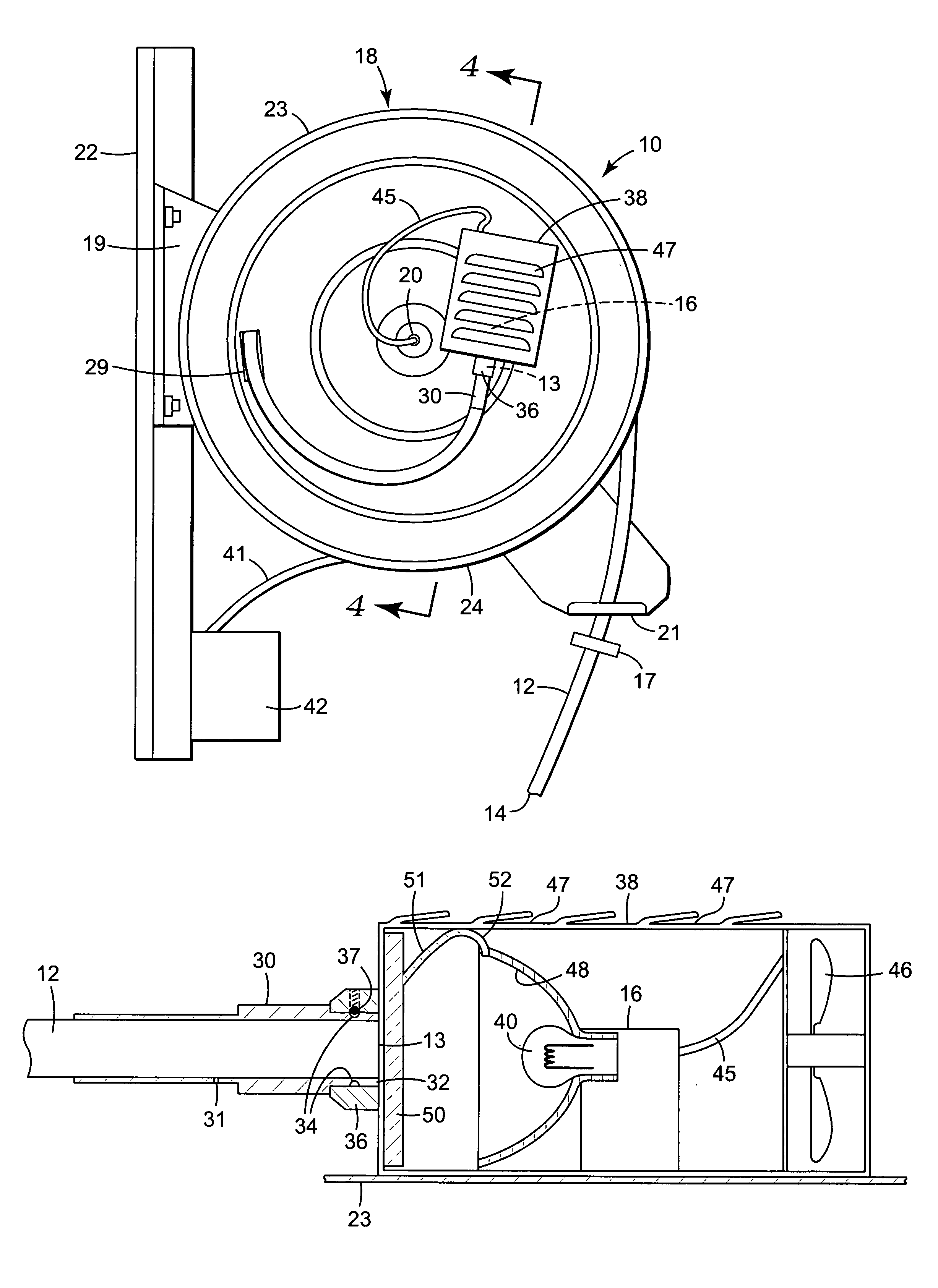
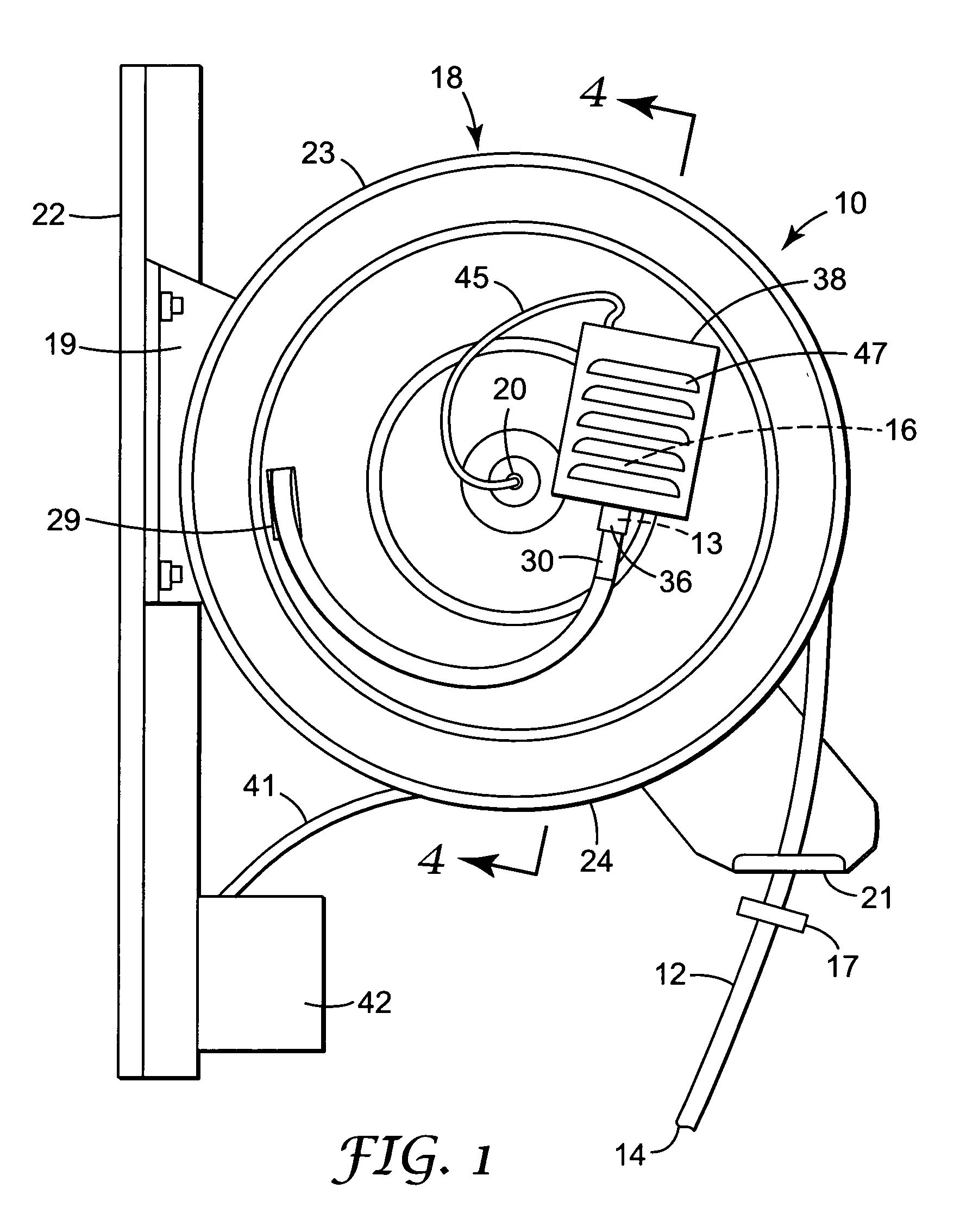
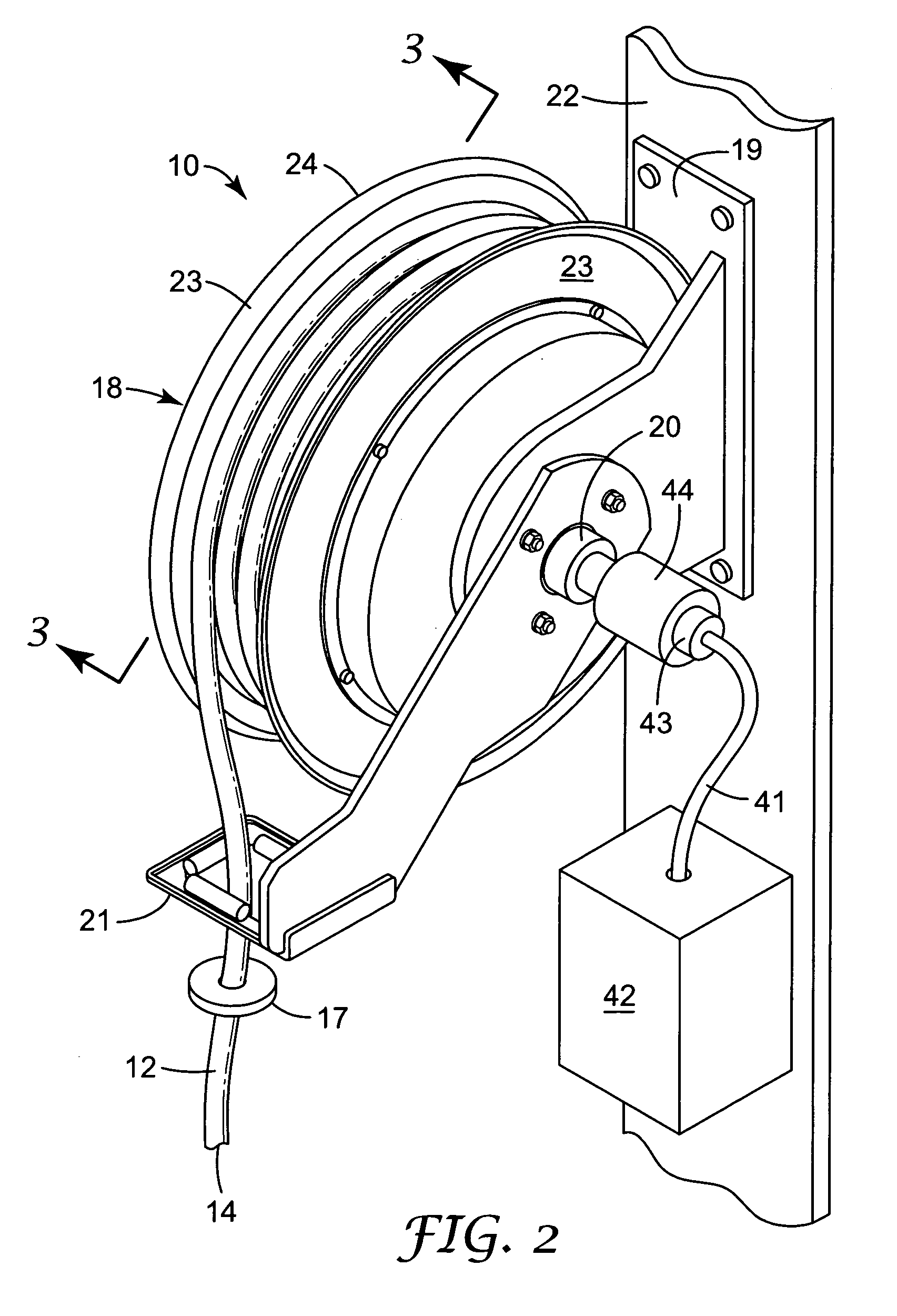
[0013]Referring now to the drawing there is illustrated a task light assembly according to the present invention generally designated by the reference numeral 10. Generally, the task light assembly 10 comprises a long elongate flexible fiber optic element 12 capable of transmitting light between its first (light inlet) and second (light outlet) ends 13 and 14; a light source 16 at the first or light inlet end 13 of the fiber optic element 12; and means for supporting the light source 16 and the light inlet end 13 of the fiber optic element 12 and for allowing movement of the fiber optic element 12 between a storage position with the second or light outlet end 14 of the fiber optic element 12 supported in a storage position, and an extended use position with the light outlet end 14 of the fiber optic element 12 at a work location remote from the storage position.

[0014]In the task light assembly 10, the means for supporting the light source 16 and the light inlet end 13 of the fiber o...


PUM


Abstract

A task light assembly including a long flexible fiber optic element capable of transmitting light between light inlet and light outlet ends; a light source at the light inlet end of the fiber optic element; and a reel assembly for supporting the light source and the light inlet end of the fiber optic element and for allowing movement of the fiber optic element between a storage position with the light outlet end of the fiber optic element supported in a storage position, and an extended use position with the light outlet end of the fiber optic element at a work location remote from the storage position.

Description

FIELD OF THE INVENTION[0001]This invention relates to sources of light (called task lights herein) that can be easily moved to illuminate a work area.BACKGROUND OF THE INVENTION[0002]When ambient lighting at a work area (e.g., the underside or motor compartment of an automobile) is insufficient, that work area can be illuminated with a task light. Commonly used task lights include portable light fixtures (sometimes called “trouble lights”) powered from an electrical distribution system that include incandescent bulbs or fluorescent tubes, and flashlights. Incandescent bulbs can provide a directed source of light, but become hot during use so that they can burn thermally sensitive materials or the user of the task light. Also, the filaments in such bulbs can be broken from even a slight impact. Fluorescent tubes generate less heat and are more impact resistant than incandescent bulbs, however the light they produce is more diffuse and not as well directed to a work area. Flashlights ...

Claims


Application Information

Patent Timeline
Patent Type & Authority Patents(United States)
IPC IPC(8): F21V27/00F21L14/02F21L14/00F21V29/02F21Y101/00G02B6/44
CPCF21L14/02F21V29/02G02B6/4457F21V29/67
Inventor GOZUM, JOHN E.REID, THOMAS J.RICHARDSON, DUANE C.
Owner 3M INNOVATIVE PROPERTIES CO
Why Eureka
Try Eureka