
Cylinder watch winder

a watch winder and cylinder technology, applied in the direction of electric winding, instruments, horology, etc., to achieve the effect of quick removal or replacemen

Inactive Publication Date: 2005-11-15
AGNOFF CHARLES
View PDF13 Cites 22 Cited by
  • Summary
  • Abstract
  • Description
  • Claims
  • Application Information

AI Technical Summary

Benefits of technology

[0007]Generally, the watch winder of the present invention is comprised of a watch carrier and a rest to support and rotate the watch carrier for predetermined periods at selected times. The watch carrier is freely supported on the rest. The term “freely supported” as used herein means that the watch carrier is only secured to the rest by the weight of the watch carrier. As a result, the carrier can be quickly removed or replaced with another watch carrier, or reversed, i.e., turned end-to-end to reverse the direction of rotation of the carrier and any watch supported within the carrier.
[0013]In operation, the user mounts a watch on the watch holder, e.g., by compressing the holder and slips the watch band around the holder with the watch face being positioned on the outer face of the holder. The holder is then inserted into either end of the cylinder with the watch recessed slightly from the cylinder end. The cylinder is then placed on the rest so that the rollers contact the surface of the cylinder. The motor is then energized either by the controller or manually with the switch, causing the cylinder to rotate.
[0014]As the cylinder rotates, the watch carried on the watch holder also rotates. The rotor, however, hangs downward and does not rotate. Therefore, the watch is wound due to the relative movement of the watch mechanism and the rotor. The motor is then de-energized after a time sufficient to wind the watch, thereby preventing potential damage to the watch mechanism. Some watches are designed to be wound clockwise, while other watches are designed to be wound counterclockwise. Both types of watches can be wound by the present invention without reversing the direction of the motor by simply reversing the orientation of the cylinder, i.e., by turning the cylinder end-to-end. The controller can also be programmed to reverse the direction of the motor at timed intervals.

Problems solved by technology

In either case when the watch is worn, the user's random and often rapid arm movements cause the rotor to swing back and forth inertially in both directions around the rotor axis, thereby winding the watch spring.
However, if the watch is not worn regularly, the user must wind the watch, either manually or with a watch winder, or the watch will stop.

Method used


Image

  • Cylinder watch winder
  • Cylinder watch winder
  • Cylinder watch winder

Examples


Embodiment Construction

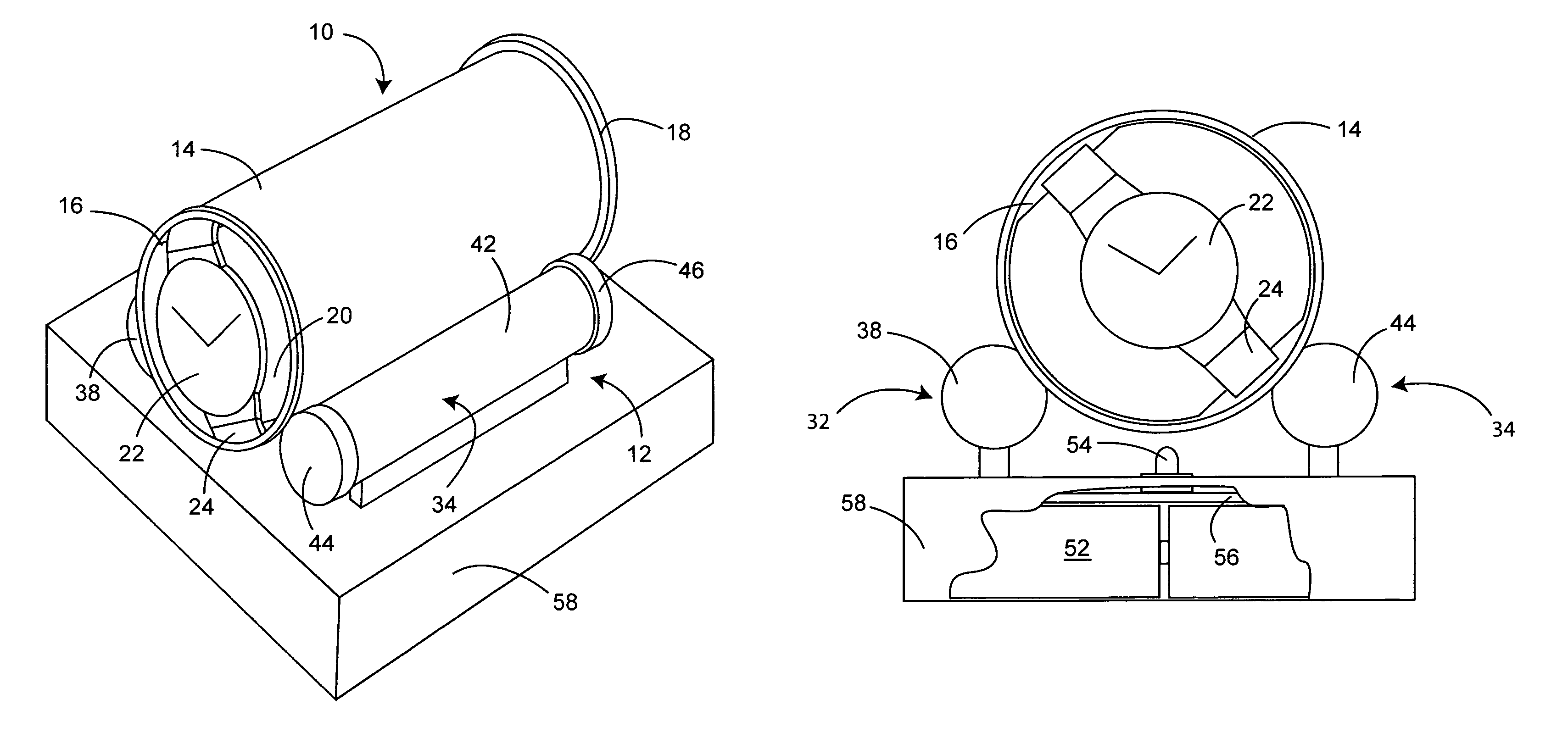
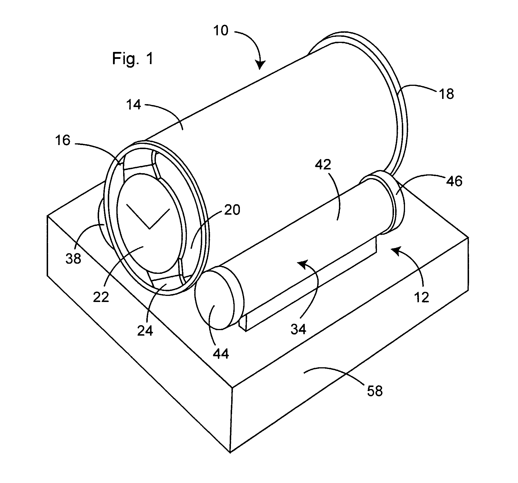
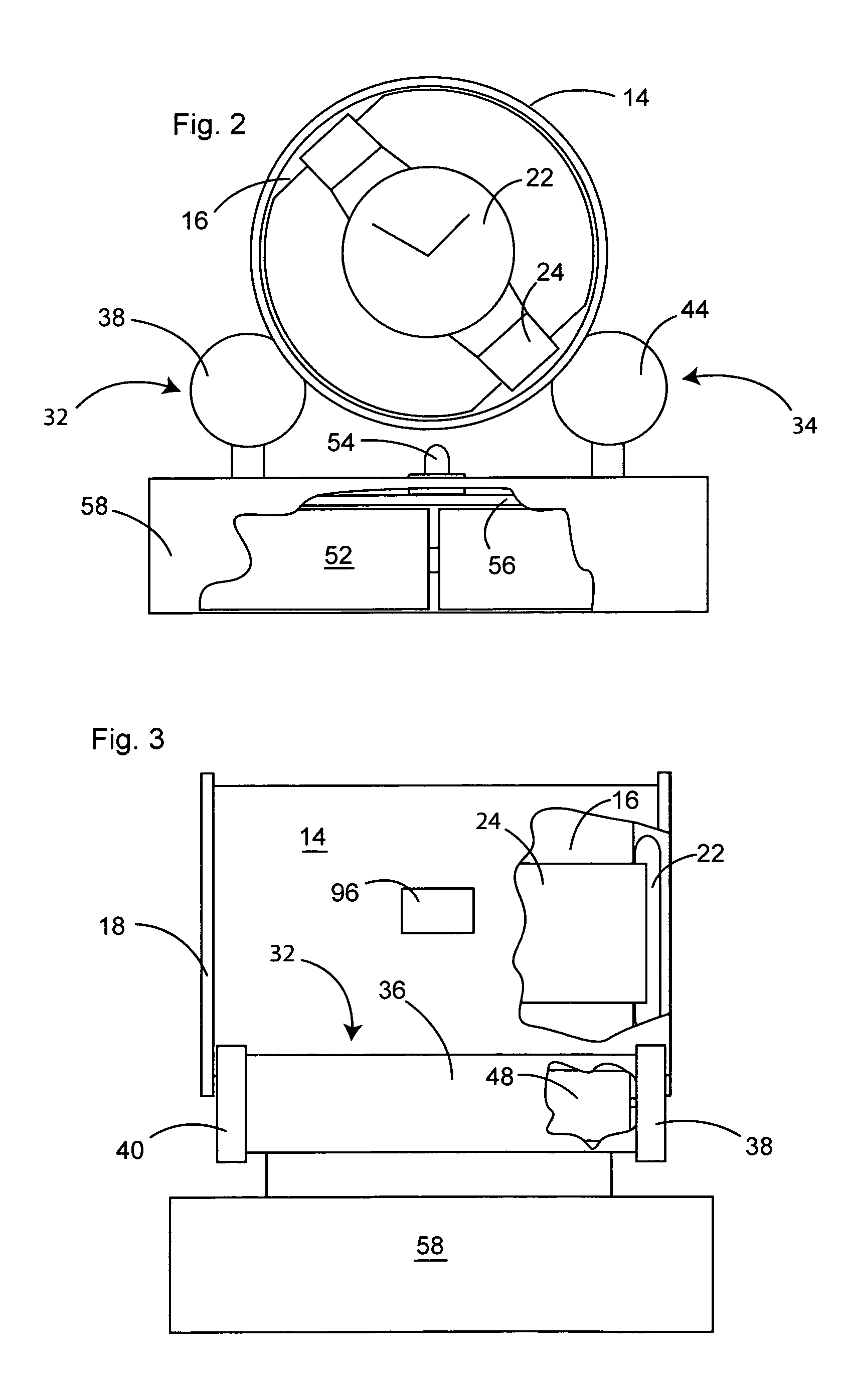
[0025]As best illustrated in FIGS. 1–3, a preferred embodiment of the watch winder of the present invention is comprised of a watch carrier, generally 10, and a rest, generally 12, to freely support watch carrier 10. Watch carrier 10 is comprised of horizontal cylinder 14 having a given diameter, a longitudinal axis, a continuous outer wall of a given length, an interior chamber defined by the inner wall of cylinder 14, and opposed ends, and watch holder 16 insertable into the interior chamber of cylinder 14. Cylinder 14 includes radial flanges 18 adjacent its ends.

[0026]Watch holder 16 includes watch-carrying face 20 perpendicular to the longitudinal axis of cylinder 14 so that watch 22 with watchband 24 can be mounted with the watch face and the plane of rotation of the rotor perpendicular to the longitudinal axis of cylinder 14. Holder 16 may be of various constructions so long as it is insertable into cylinder 14.

[0027]Rest 12 is comprised of first and second support sections 32...


PUM


Abstract

A watch winder includes a watch carrier that is freely supported on a rest for ease in mounting and removing the carrier and for reversing the direction of winding by simply turning the watch carrier end-to-end. The watch carrier includes a cylinder and a watch holder insertable into the interior of the cylinder. The rest is adapted to support the cylinder in a horizontal position, and includes first and second support sections having parallel longitudinal axes spaced from each other at a distance less than the diameter of the cylinder. Each section includes a housing having rollers or other support surfaces adjacent the ends of the housing, with at least one of the rollers being driven by an electric motor to rotate the cylinder at predetermined times when the cylinder is supported on the rollers. A feature of the cylinder may be detected to stop rotation at a predetermined orientation.

Description

BACKGROUND OF THE INVENTION[0001](1) Field of the Invention[0002]The present invention relates generally to automatic watch winders for winding self-winding watches, and in particular to watch winders enabling easy mounting and removal of the watch, and the ability to position the watch carrier in either direction so that watches with different winding characteristics, e.g., clockwise or counterclockwise rotation, can be wound on the same watch winder without changing the settings of the watch winder.[0003](2) Description of the Prior Art[0004]The winding mechanism of a self-winding watch is comprised of a bearing mounted pendulum or rotor that is connected through a gear reduction system to the mainspring of the watch. Generally, the rotor can rotate 360° in either direction. However, there are also so-called “hammer” shaped rotors in older self-winding watches that have a limited travel of 150° to 220° rotation. In either case when the watch is worn, the user's random and often ra...

Claims


Application Information

Patent Timeline
IPC IPC(8): B01F11/00G09B3/00G09D3/00G04B3/00G04D7/00
CPCG04B3/006G04D7/00G04D7/009
Inventor AGNOFF, CHARLES
Owner AGNOFF CHARLES
Learn More