
Output-split and compound-split infinitely variable transmission

a transmission and output technology, applied in fluid gearings, electric propulsion mountings, gearing, etc., can solve the problems of reducing the efficiency of the overall drive line, affecting the driving comfort, and affecting the transmission quality, so as to avoid internal power circulation and extend the speed ratio range

Inactive Publication Date: 2005-11-15
THE TIMKEN CO
View PDF9 Cites 27 Cited by
  • Summary
  • Abstract
  • Description
  • Claims
  • Application Information

AI Technical Summary

Benefits of technology

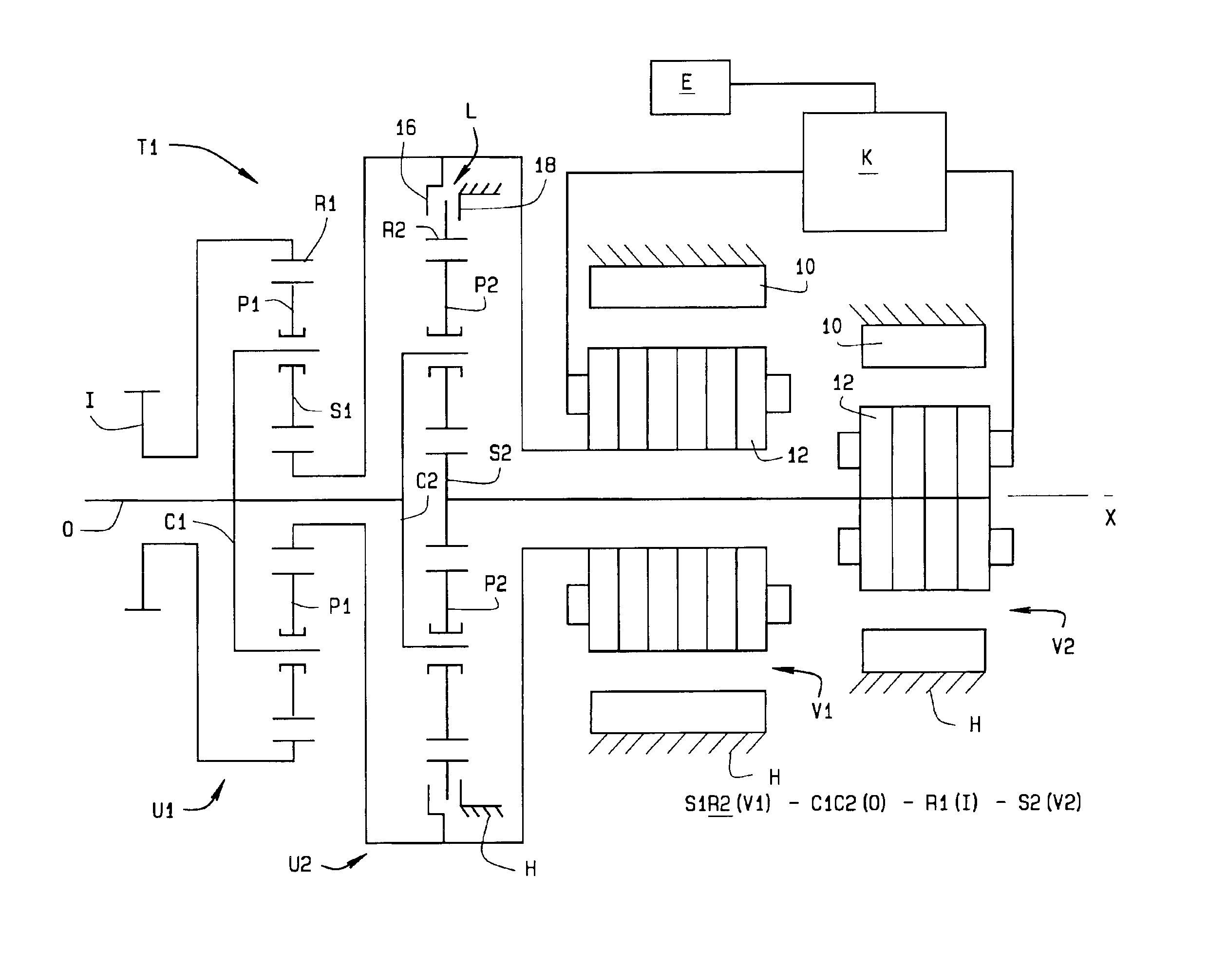
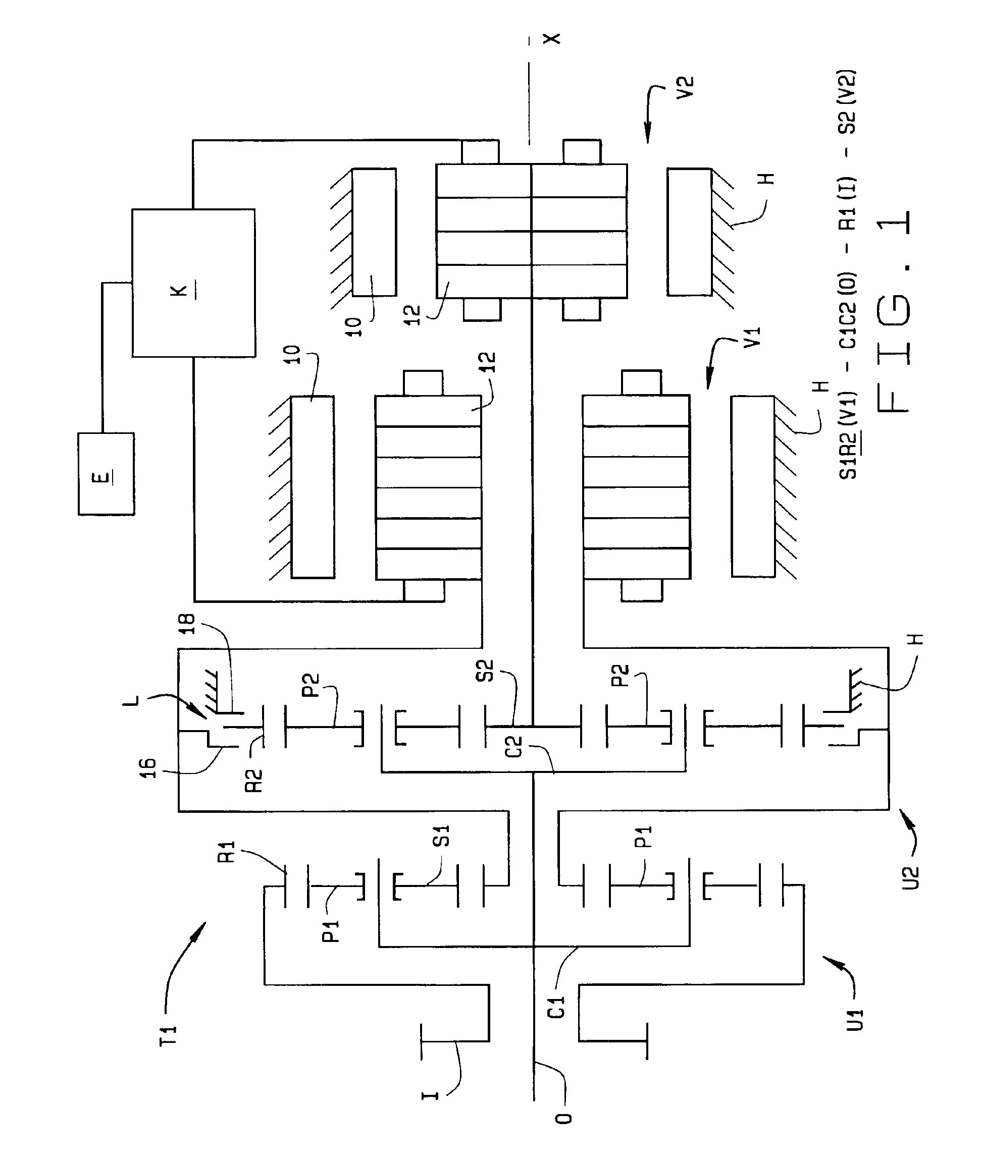
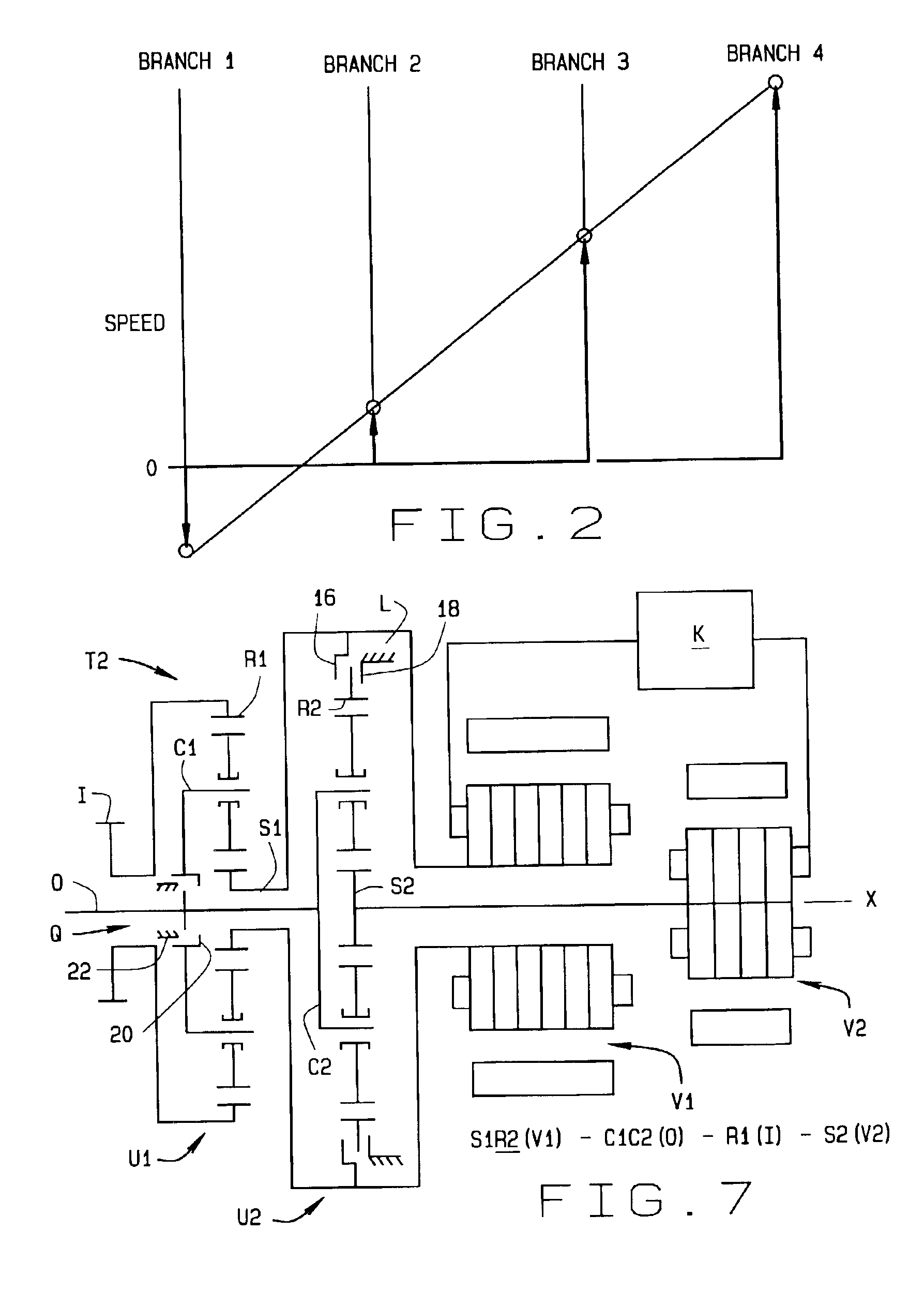
[0013]The present invention resides in a transmission having two planetary units and two variators, all connected together such that power is transferred between an input and an output in a compound split mode. With a clutch, the transmission is reconfigured to transfer power in an output split mode, thus, extending the speed ratio range and avoiding internal power circulation. The invention also resides on the process employed by the transmission to transfer power.

Problems solved by technology

Therefore, it is not always possible to use the maximum available engine power, because engine speed and load vary as the transmission moves through its limited number of fixed ratios.
Moving from one ratio to another is sometimes termed “shifting” in transmission design descriptions, and is often associated with unfavorable torque interruptions.
Such interruptions offset overall drive-line efficiency and detract from driving comfort.
Moreover, for some applications, such as agricultural and construction vehicles, an output torque interruption is extremely undesirable, more so than a momentary loss of efficiency.
In principle, a stepwise transmission cannot achieve the overall vehicle efficiency of a step-less transmission which offers an infinite number of speed ratios.
In addition, most of the CVT designs transmit torque through contacting friction surfaces and are not suitable for high-torque and high-power applications.
However, hydrostatic transmissions are very inefficient, particularly under partial load and slow speeds, and are often noisy.
It wastes power, generating unwanted heat within the transmission.

Method used


Image

  • Output-split and compound-split infinitely variable transmission
  • Output-split and compound-split infinitely variable transmission
  • Output-split and compound-split infinitely variable transmission

Examples


Embodiment Construction

[0025]A transmission T (FIG. 1) having infinite speed ratios operates in two modes —namely, an output-split mode and a compound-split mode—depending on several factors including output speed and power demands. To this end, the transmission T in each of its modes transfers power through two paths—specifically, through a purely mechanical path and through a variator path. The mechanical path in and of itself provides no basis for varying the speed ratio of the transmission T. The variator path does that for both modes of operation. Thus, the transmission T operates on a power split principle. When in the output-split mode, the transmission T has its greatest input-to-output ratio, that is to say its lowest output speeds. While the transfer of power occurs generally through both the mechanical path and the variator path, as the output speed increases, the transfer of power comes to a point or node during which all of the transfer occurs in the mechanical path. When in the compound spli...


PUM


Abstract

A transmission includes two planetary units (U1, U2) and two variators (V1, V2), all connected together such that power can be transferred between an input (I) and an output (O) in a compound-split mode or an output-split mode. In the compound-split mode the two planetary units are joined together at two connections, creating two compound member branches and two single member branches. Except when the transmission operates at its nodes, power transfers through a mechanical path and also through a variator path located in part between the two variators, one of which functions as a motor and the other as the source of power for the motor. At the nodes all power transfers through the mechanical path and the transmission has its greatest efficiency. In the output-split mode, which exists at an output speed below that identified with the first node, one of the compound member branches is interrupted so that the two planetary units are only coupled at one of the compound member branches. In this mode some of the power transfers through the first planetary unit, and some transfers through the variators and the second planetary unit.

Description

CROSS-REFERENCE TO RELATED APPLICATIONS[0001]This application derives priority from U.S. provisional application No. 60 / 367,913, filed Mar. 26, 2002, and entitled “Output / Compound Split Infinitely Variable Transmission.”STATEMENT REGARDING FEDERALLY SPONSORED RESEARCH OR DEVELOPMENT[0002]Not Applicable.BACKGROUND OF THE INVENTION[0003]This invention relates in general to transmissions for transmitting rotary motion and, more particularly, to an output split and compound split infinitely variable transmission.[0004]The primary function of a transmission in an automotive vehicle is to convert the speed and torque of an engine or prime mover into the speed and torque required by the specific requirements of the vehicle. In general it is desirable for this power transmission to occur with minimal power loss; that is, at high transmission efficiency. To optimize the overall power train efficiency, specifically the engine-transmission combination, it is also desirable to minimize or to el...

Claims


Application Information

Patent Timeline
IPC IPC(8): B60K6/04B60K6/00F16H3/72F16H3/44B60K1/02B60K1/00B60K6/365B60K6/445F16H47/04
CPCB60K6/365B60K6/445F16H3/728B60K1/02F16H47/04F16H2037/0866F16H2037/104F16H2037/106F16H2200/2007Y02T10/6239Y02T10/62
Inventor AI, XIAOLANMOHR, TERRY W.
Owner THE TIMKEN CO
Learn More