Method for monitoring the transmission quality of an optical transmission system, in particular of an optical wavelength-division multiplex network

a transmission quality and optical transmission technology, applied in transmission monitoring, electrical equipment, electromagnetic transmission, etc., to achieve the effect of improving the transmission quality of optical transmission systems, achieving optimal support, and obtaining results much faster

Inactive Publication Date: 2005-11-15
DEUTSCHE TELEKOM AG
View PDF1 Cites 9 Cited by
  • Summary
  • Abstract
  • Description
  • Claims
  • Application Information

AI Technical Summary

Benefits of technology

[0024]Thus, there should be no need to develop any mathematical algorithms to provide information about the type of fault that may be occurring and the degree of signal degradation. All signals may be analyzed without knowledge of the transfer format and / or the timing (or clock pulse). For that reason, the transparency of optical transmission systems, such as WDM networks, may be optimally supported and not restricted. Since neural networks may be massively parallel structures, the exemplary embodiments and / or exemplary methods of the present invention should provide for obtaining results much more rapidly than by using a mathematical algorithm. It is believed that another benefit of the exemplary method is that even when assessing unknown, unanticipated input models, meaningful output values may be derived.

Problems solved by technology

This information may be essentially found in the amplitude distribution and may be lost when an analysis is made at the digital level.

Method used


Image

  • Method for monitoring the transmission quality of an optical transmission system, in particular of an optical wavelength-division multiplex network
  • Method for monitoring the transmission quality of an optical transmission system, in particular of an optical wavelength-division multiplex network
  • Method for monitoring the transmission quality of an optical transmission system, in particular of an optical wavelength-division multiplex network

Examples


Embodiment Construction

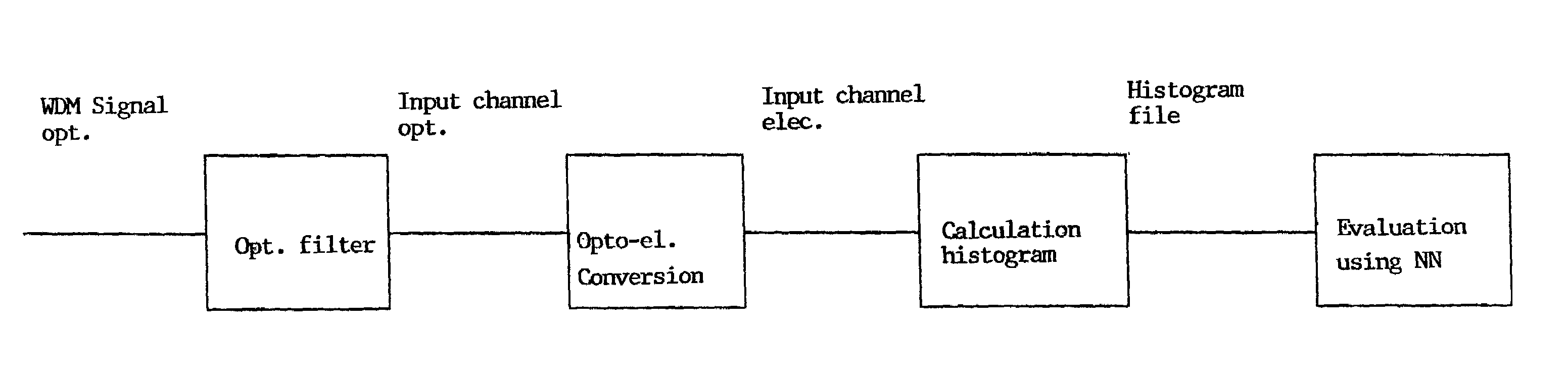
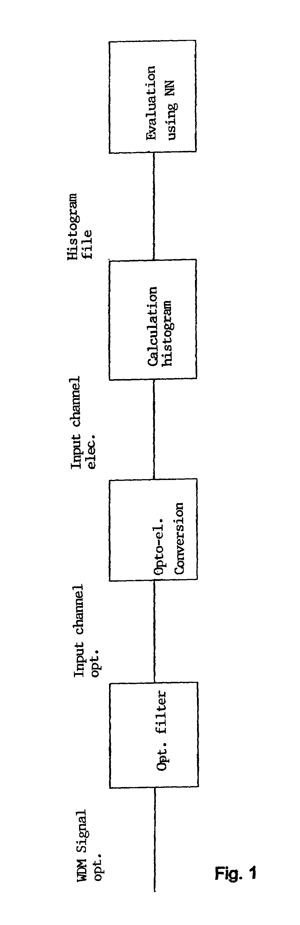
[0028]FIG. 1 shows a block diagram of an exemplary method according of the present invention. From an optical WDM signal, which may be composed of a multiplicity of wavelength components, an optical channel may be selected with the aid of an optical filter. Consequently, only light in a specific wavelength range transmitted by the filter may fall on (or strike) an optoelectronic transducer device. The transducer device may be a photodetector or a photodiode having a high bandwidth, so that even rapid changes in the optical signal can be detected. For example, a photodiode having a 20 Ghz receiving bandwidth may be used.

[0029]The transducer device may emit an electric output signal, whose time characteristic may essentially correspond to that of the optical transmission signal of the detected wavelength. This electronic output signal may be sampled asynchronously, the signal height being measured at arbitrary points in time, in each case, integrated over a time slot of a predefined l...


PUM


Abstract

A method for monitoring the transmission quality of an optical transmission system, such as, for example, an optical wavelength division-multiplex network. An amplitude histogram of an optical signal (transmission signal) transmitted over the transmission system may be plotted and classified, with the assistance of a neural network, according to bit error rates and/or causes of faults. The need for setting requirements for transmission mode, transmission format and/or transmission timing cycle of the transmission system may be eliminated. The amplitude histogram may be implemented for any signal, and causes of faults, which are not able to be determined by a conventional bit rate classification, may be allocated.

Description

[0001]This application is a 371 of PCT / EP00 / 00420, filed Jan. 20, 2000.FIELD OF THE INVENTION[0002]The present invention is directed to a method for monitoring the transmission quality of an optical transmission communications system, in particular of an optical wavelength-division multiplex network.BACKGROUND INFORMATION[0003]In optical transmission systems including, for example, in optical wavelength division-multiplex systems (WDM systems), the problem may arise of having to monitor the transmission quality, in order to guarantee a certain (quality of service—QoS) and to be able to detect slow system degradations. Transparent, optical wavelength division-multiplex systems may be increasingly used, perhaps because they are believed to significantly increase the capacity and flexibility of today's information and telecommunications networks. Not only is an optical signal of a single wavelength transmitted via an optical fiber, but, by employing a plurality of wavelengths, a plural...

Claims


Application Information

Patent Timeline
Patent Type & Authority Patents(United States)
IPC IPC(8): H04B10/08H04B10/00H04B10/02H04B10/079
CPCH04B10/07953
Inventor HANIK, NORBERTSCHMID, HERBERT
Owner DEUTSCHE TELEKOM AG
Why Eureka
Try Eureka