Magnetic levitation bed

a magnetic levitation and bed technology, applied in the field of beds, can solve the problems of motor burnout, motor parts may injure users or operators accidentally, driving motors consume a lot of electric energy,

Inactive Publication Date: 2005-11-22
CHENG SHAO SZU
View PDF1 Cites 41 Cited by
  • Summary
  • Abstract
  • Description
  • Claims
  • Application Information

AI Technical Summary

Benefits of technology

[0007]The magnetic levitation bed of the present invention has the magnets at the bed frame and the magnets at the base form “repulsive magnetic levitation mechanism” and “attractive magnetic levitation mechanism”. Further, the permanent magnets at the bed frame and the electromagnets at the base provide a “magnetic compensatory and conductive technique”. This design has the advantages of high magnetic levitation, low energy consumption, high machine reliability, high operation convenience, and low manufacturing cost.
[0014]3. Easy maintenance: because no linking mechanism is provided between the bed frame and the base, the bed frame does not touch the base during its motion. Because no friction resistance is produced between the bed frame and the base, the magnetic levitation bed is durable and reliable. Maintenance work is mainly at electronic techniques without much labor.

Problems solved by technology

During operation, the moving parts of the mechanism may injure the user or operator accidentally.
Further, the driving motor consumes much electric energy and produces a big noise during operation.
The motor may be burned out when overload or if the operator forgot to turn off power supply.

Method used


Image

  • Magnetic levitation bed
  • Magnetic levitation bed
  • Magnetic levitation bed

Examples


Embodiment Construction

[0023]The following descriptions are of exemplary embodiments only, and are not intended to limit the scope, applicability or configuration of the invention in any way. Rather, the following description provides a convenient illustration for implementing exemplary embodiments of the invention. Various changes to the described embodiments may be made in the function and arrangement of the elements described without departing from the scope of the invention as set forth in the appended claims.

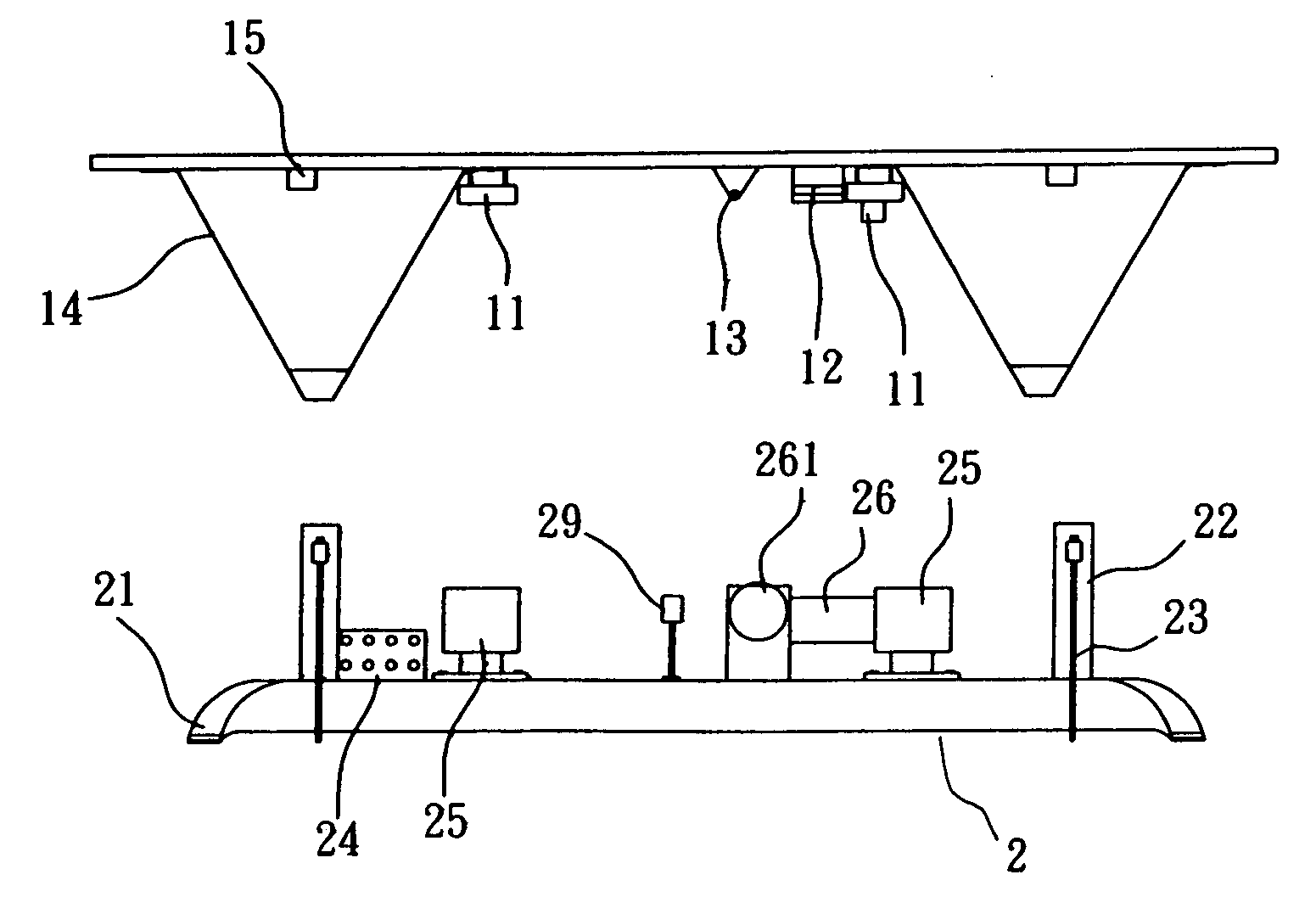
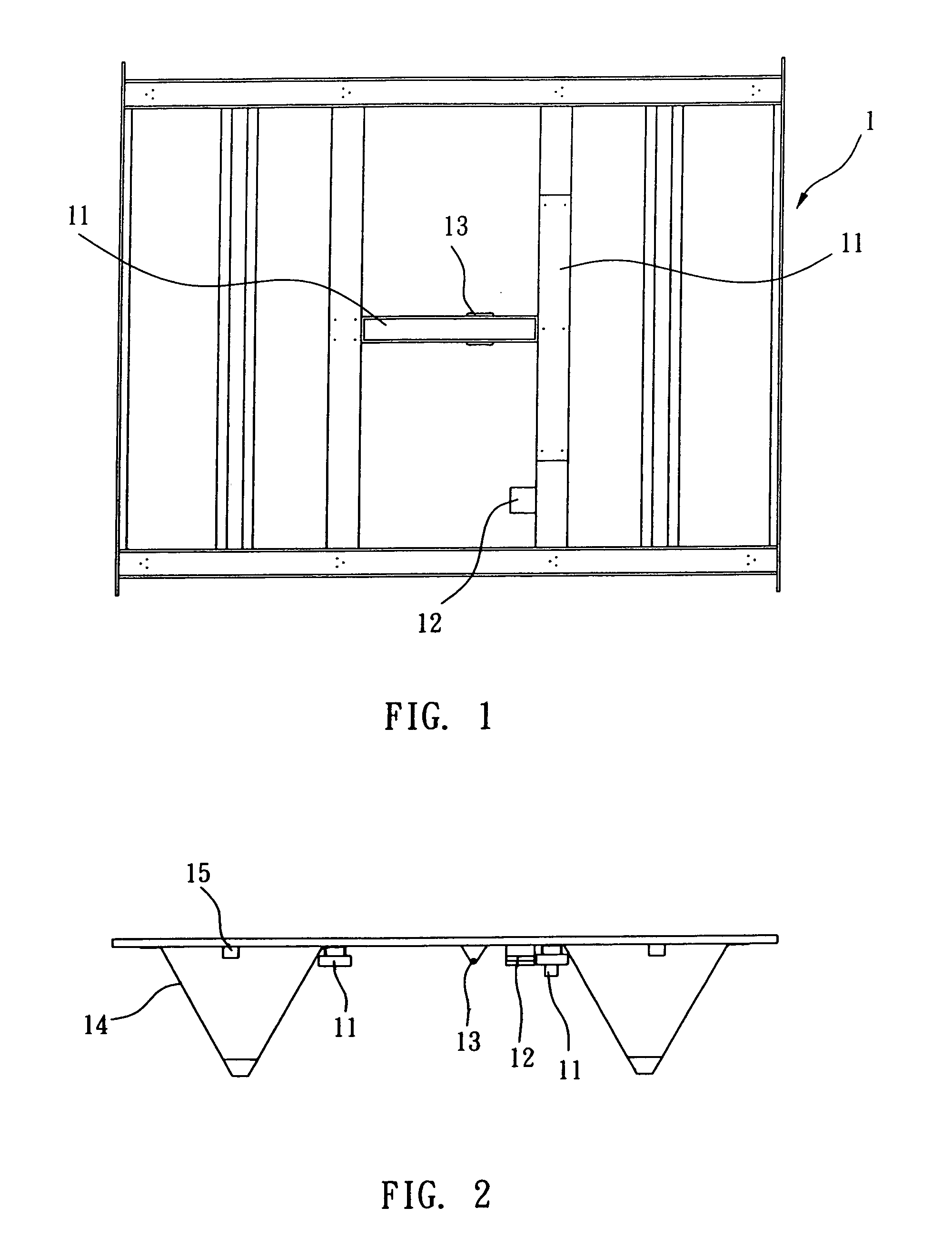
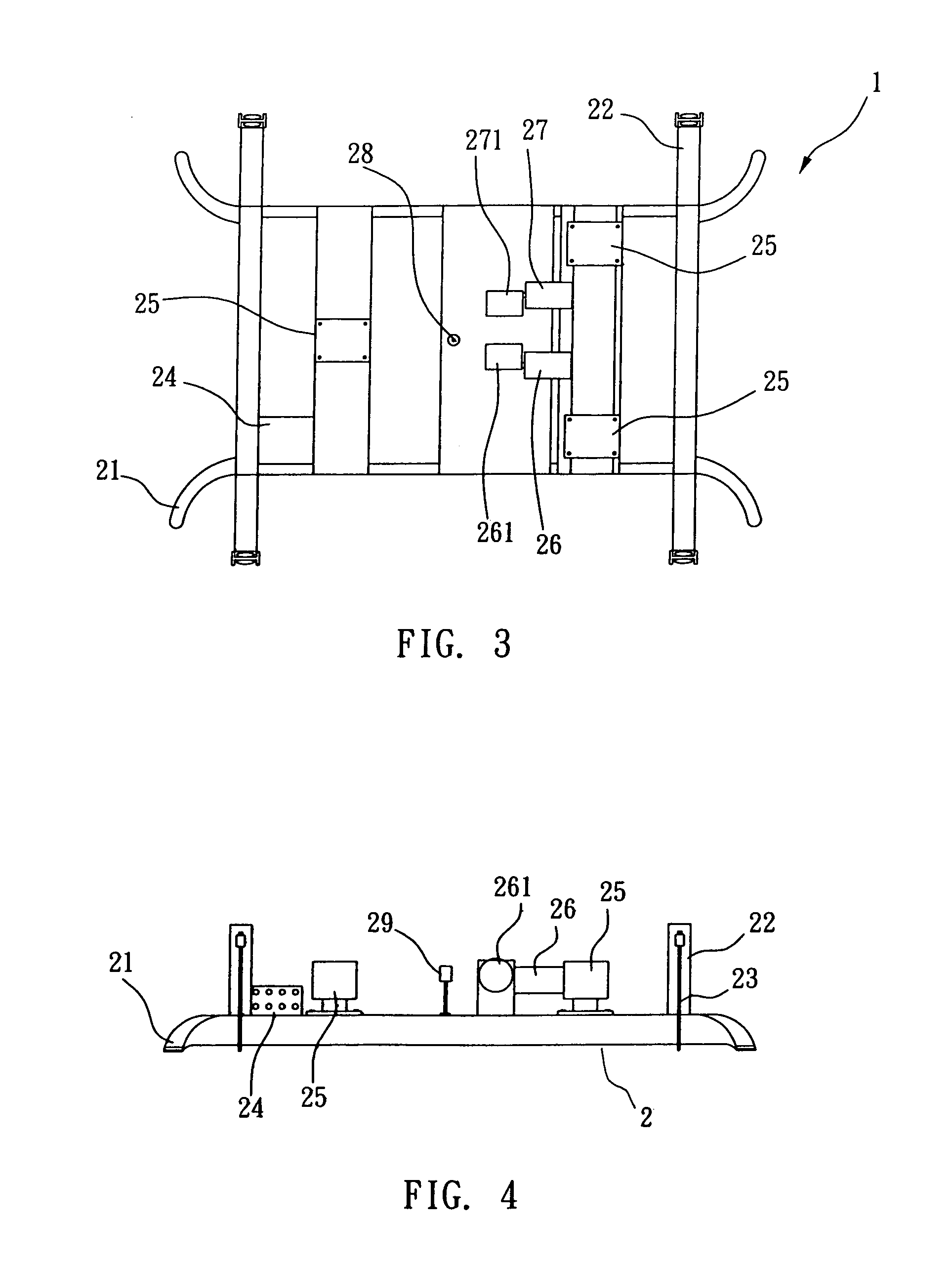
[0024]Referring to FIGS. 1˜4, a magnetic levitation bed in accordance with the present invention is comprised of a bed frame 1 and a base 2.

[0025]Referring to FIGS. 1 and 2, the bed frame 1 is a framework of tough material. If desired, the bed frame 1 can be attached with a headboard, sideboards, a footboard, a stereo system, a remote controller, and a mattress. The bed frame 1 has a plurality of foot members 14 downwardly extending from the bottom wall, a plurality of rubber pads 15 provided at ...


PUM


Abstract

A magnetic levitation bed is disclosed to include a bed frame, which is equipped with a plurality of permanent magnet arrays, a first cam-fitting mechanism, and a second cam-fitting mechanism, and a base, which is equipped with a power control box controllable by a remote controller, a plurality of electromagnet arrays arranged corresponding to the permanent magnet arrays and controllable by the control box to attract and repulse the permanent magnet arrays, a first low-speed motor controllable by the power control box to turn a first cam relative to the first cam-fitting mechanism and to further cause the bed frame to oscillate in transverse direction, a second low-speed motor controllable by the power control box to turn a second cam relative to the second cam-fitting mechanism and to further cause the bed frame to oscillate in longitudinal direction, and sensors for detecting oscillation of the bed frame and providing a signal indicative of the position change of the bed frame to a microprocessor for enabling the power control box to control the operation of the first low-speed motor or second low-speed motor subject to the data received from the sensors.

Description

BACKGROUND OF THE INVENTION[0001](a) Technical Field of the Invention[0002]The present invention relates to a bed and more particularly to, a magnetic levitation bed, which enables the bed frame to be suspended on a magnetic cushion and oscillated transversely / longitudinally.[0003](b) Description of the Prior Art[0004]Conventional massaging beds are commonly made in the form of a waterbed or aircushion bed in which links, gears, transmission belts, transmission chains are provided between the bed frame and the base and driven to move the bed frame relative to the base. A hydraulic mechanism may be used and controlled to oscillate the bed frame relative to the base. These conventional designs use motor to drive the transmission or hydraulic mechanism. During operation, the moving parts of the mechanism may injure the user or operator accidentally. Further, the driving motor consumes much electric energy and produces a big noise during operation. The motor may be burned out when overl...

Claims


Application Information

Patent Timeline
Patent Type & Authority Patents(United States)
IPC IPC(8): A61G7/00A47C21/00A61G7/057A61H1/00
CPCA47C21/006A47C31/003A61G7/0573A61H1/001A61H1/003A61H2201/0142A61H2203/0443
Inventor CHENG, SHAO-SZU
Owner CHENG SHAO SZU
Why Eureka
Try Eureka