Irregular surfaced tape guide

a tape guide and irregular surface technology, applied in the field of flanged tape guides, can solve the problems of distorting or otherwise damaging the tape, the head may not be able to follow the the read/write head positioning system may have difficulty following such high frequency tape movement, so as to minimize the distortion of the tape

Inactive Publication Date: 2005-11-22
HEWLETT-PACKARD ENTERPRISE DEV LP
View PDF13 Cites 5 Cited by
  • Summary
  • Abstract
  • Description
  • Claims
  • Application Information

AI Technical Summary

Benefits of technology

[0008]The present invention is directed to a tape guide that has a textured roughness exceeding the flying height of the tape above the surface. This new irregular surface topography reduces the air bearing and allows limited contact between the tape guide and the tape while minimizing tape distortion that can occur with other surface topographies.

Problems solved by technology

If the tape is presented to the head at too great an angle, then the read and write elements in the head may be misaligned to the data tracks.
Read / write head positioning systems have difficulty following such high frequency tape movement.
It has been discovered that these surface topographies can leave imprints on the tape which may, under some conditions, distort or otherwise damage the tape.

Method used


Image

  • Irregular surfaced tape guide
  • Irregular surfaced tape guide
  • Irregular surfaced tape guide

Examples


Embodiment Construction

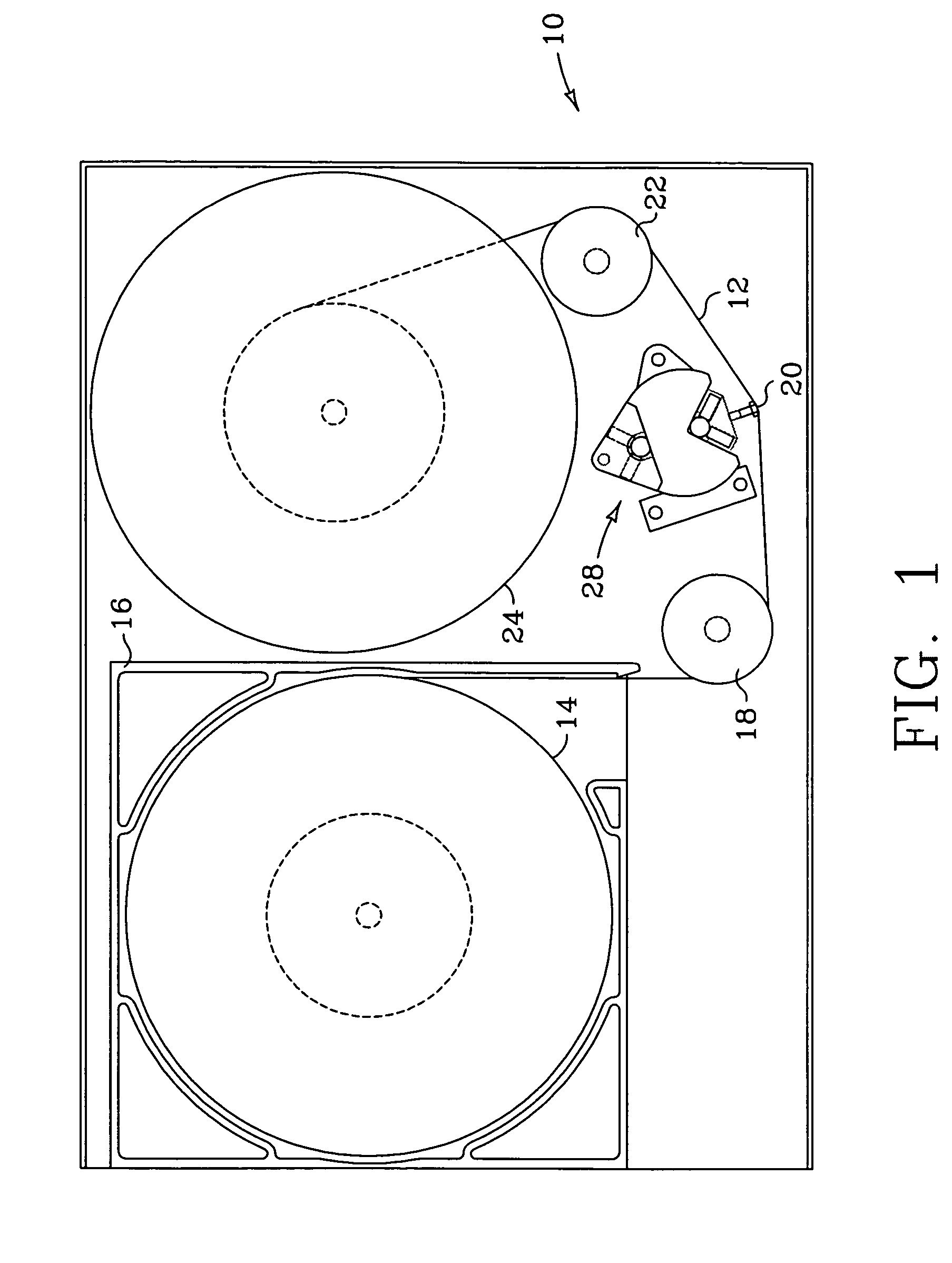
[0022]As noted above, FIG. 1 illustrates generally the configuration of a tape drive 10 typical of those used with single spool tape cartridges. Referring again to FIG. 1, a magnetic tape 12 is wound on a single supply spool 14 in tape cartridge 16. Tape cartridge 16 is inserted into tape drive 10 for read and write operations. Tape 12 passes around a first tape guide 18, over a magnetic read / write head 20, around a second tape guide 22 to a take up spool 24. Head 20 is mounted to a carriage and actuator assembly 26 that positions head 20 over the desired track or tracks on tape 12. Head 20 engages tape 12 as tape 12 moves across the face of head 20 to record data on tape 12 and to read data from tape 12.

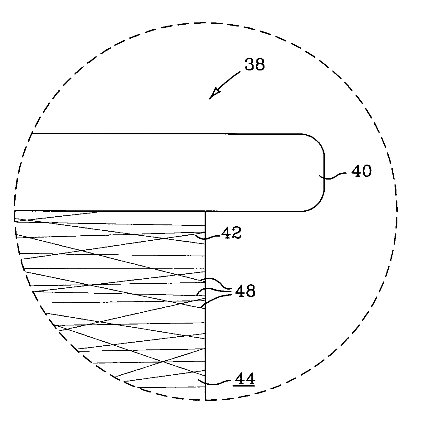
[0023]A tape guide constructed according to one embodiment of the present invention is shown in FIGS. 4–5. Referring to FIGS. 4–5, each roller guide 38 includes disc shaped flanges 40 and an annular hub 42. Tape 12 rides on the outer surface 44 of hub 42. Each flange 40 extends radi...


PUM

PropertyMeasurementUnit
surface roughnessaaaaaaaaaa
widthaaaaaaaaaa

Abstract

A tape guide that has textured surface over which the tape passes. The textured surface has a surface roughness exceeding the flying height of the tape above the surface. This new irregular surface topography reduces the air bearing and allows limited contact between the tape guide and the tape while minimizing tape distortion that can occur with other surface topographies.

Description

CROSS REFERENCE TO RELATED APPLICATIONS[0001]This is a continuation of application Ser. No. 09 / 992,717 filed Nov. 14, 2001 now abandoned.FIELD OF THE INVENTION[0002]The present invention relates generally to tape drives and, more particularly, to flanged tape guides that have an irregular surface to reduce the air bearing between the tape and the surface of the hub.BACKGROUND OF THE INVENTION[0003]Information is recorded on and read from a moving magnetic tape with a magnetic read / write head positioned next to the tape. The magnetic “head” may be a single head or, as is common, a series of read / write head elements stacked individually and / or in pairs within the head unit. Data is recorded in tracks on the tape by moving the tape lengthwise past the head. The head elements are selectively activated by electric currents representing the information to be recorded on the tape. The information is read from the tape by moving the tape longitudinally past the head elements so that magneti...

Claims


Application Information

Patent Timeline
Patent Type & Authority Patents(United States)
IPC IPC(8): G11B15/67G11B15/66G11B15/60
CPCB65H55/043G11B15/605G11B15/67
Inventor BLOOMQUIST, DECEASED, DARREL R.BLOOMQUIST, LEGAL REPRESENTATIVE, JUDY
Owner HEWLETT-PACKARD ENTERPRISE DEV LP
Why Eureka
Try Eureka