Rotating circular die

Inactive Publication Date: 2005-11-22
FRITO LAY NORTH AMERICA INC
View PDF10 Cites 1 Cited by
  • Summary
  • Abstract
  • Description
  • Claims
  • Application Information

AI Technical Summary

Benefits of technology

[0014]The proposed invention comprises a rotating circular die assembly for use with an extruder that provides a means to easily adjust the thickness of the extrudate during processing and eliminates sanitary problems associated with housing the die assembly within the extruder passageway.
[0016]In order to achieve the desired thickness of extrudate, the opening of the annular die channel formed between the inner and outer components can be easily varied by adjusting the position of the inner component forward or backward in relation to the outer component. Further adjustment of the position of the inner component allows easy access to the extruder and die for cleaning purposes and for clearing extrudate clogs. In addition, the inner component has a tendency towards self-centering, thereby producing extrudate of uniform thickness. While rotating, the die is self-clearing and capable of imparting rotational shearing stresses on the extrudate in order to provide for starch alignment in the direction of such stress. The inner component may be used as a rotational viscometer by monitoring the torque on same and / or a mechanical force sensor by monitoring the linear force exerted against the component, thus allowing for precise viscosity and pressure measurements directly at the die to be used as process indicators of extrudate flow at the die. If undesired measurements are obtained, adjustments to the composition of the extrudate may be made at the extruder opening or action can be taken to prevent clogs and extrudate backup. Furthermore, the components may house devices used to heat and / or cool the contact surfaces of the outer and inner cones independently to produce differences in structure, appearance and texture of the extruded product.

Problems solved by technology

As a result, the flow rate can be lower at the edges than in the center of the channel, resulting in non-uniform extrudate.
In addition, undesired thickness variations in the extrudate can be found in the die channel direction as well as in the direction of extrusion.
However, the circular die does not offer the flexibility of easily adjusting the die components to vary the thickness of the extrudate.
This lengthy process is cumbersome and also costly to manage, for production must be suspended until the replacement is installed.
However, the rotation speed of the die components cannot exceed a certain threshold wherein the serrated edges no longer impart distinct ridges and valleys on the surfaces of the extrudate.
Clogs of extrudate can form in the extruder passageway and become caught in the die channel.
As a result, the normal flow of extrudate is hampered and a backup occurs in the passageway.
Although the Budd et al. device avoids the thickness variation problems inherent in the linear die for the same reasons as does the fixed circular die, the thickness of the extrudate exiting from die cannot be adjusted without replacing the inner or outer component with one with different dimensions.
This is a time-consuming operation and processing cannot resume until after the die is dismantled and reassembled with the new die component.
Such cleaning, unclogging or component replacement times can result in reduced production and costly production down time.
Placement of the inner facing components within the extruder can be problematic, however, since the inner facing components have additional surfaces to which food particles can adhere.
This may result in additional or increased extruder cleaning periods and thus shortened production periods.
In addition, the direct contact between the extrudate and the bearings and seals of the housings may result in sanitary and microbial spoilage issues.

Method used


Image

  • Rotating circular die
  • Rotating circular die
  • Rotating circular die

Examples


Embodiment Construction

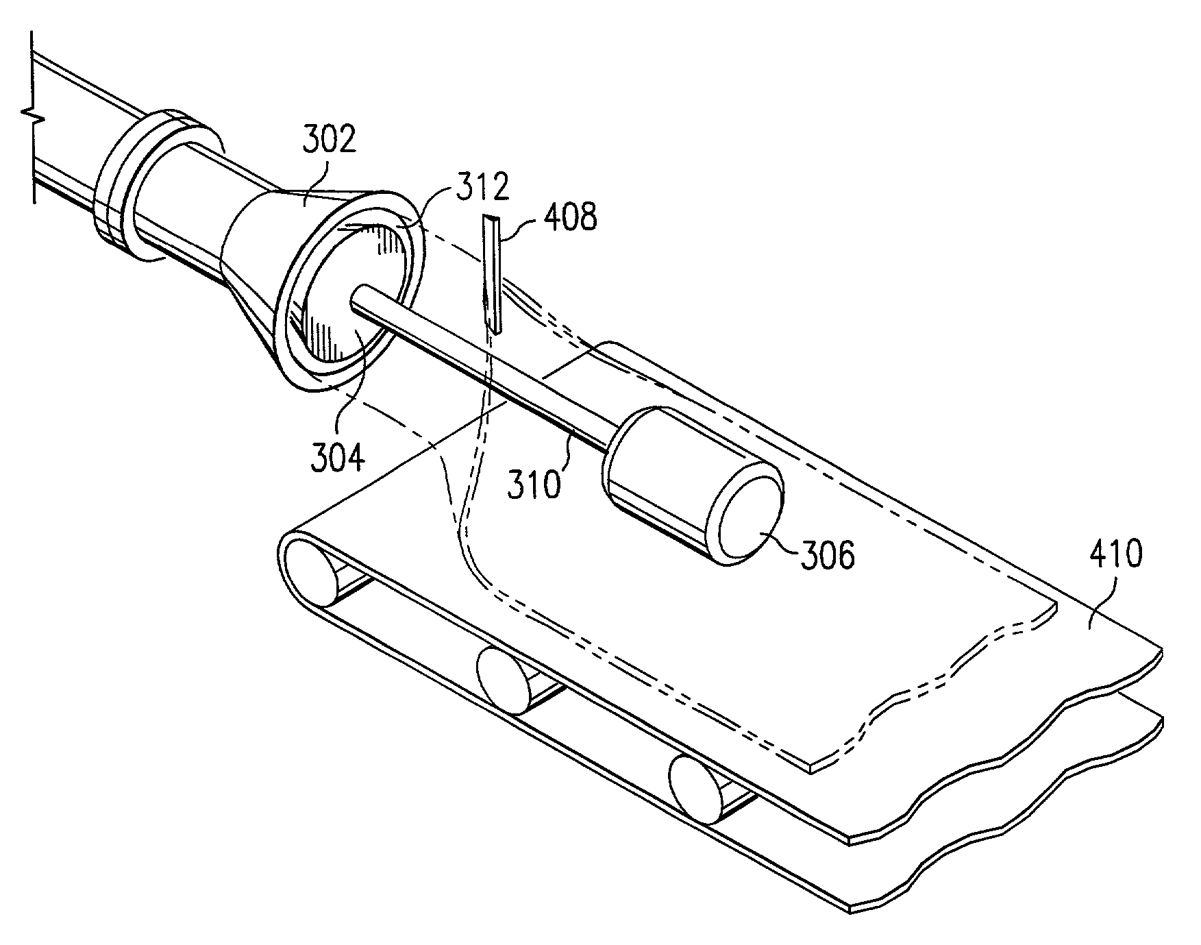
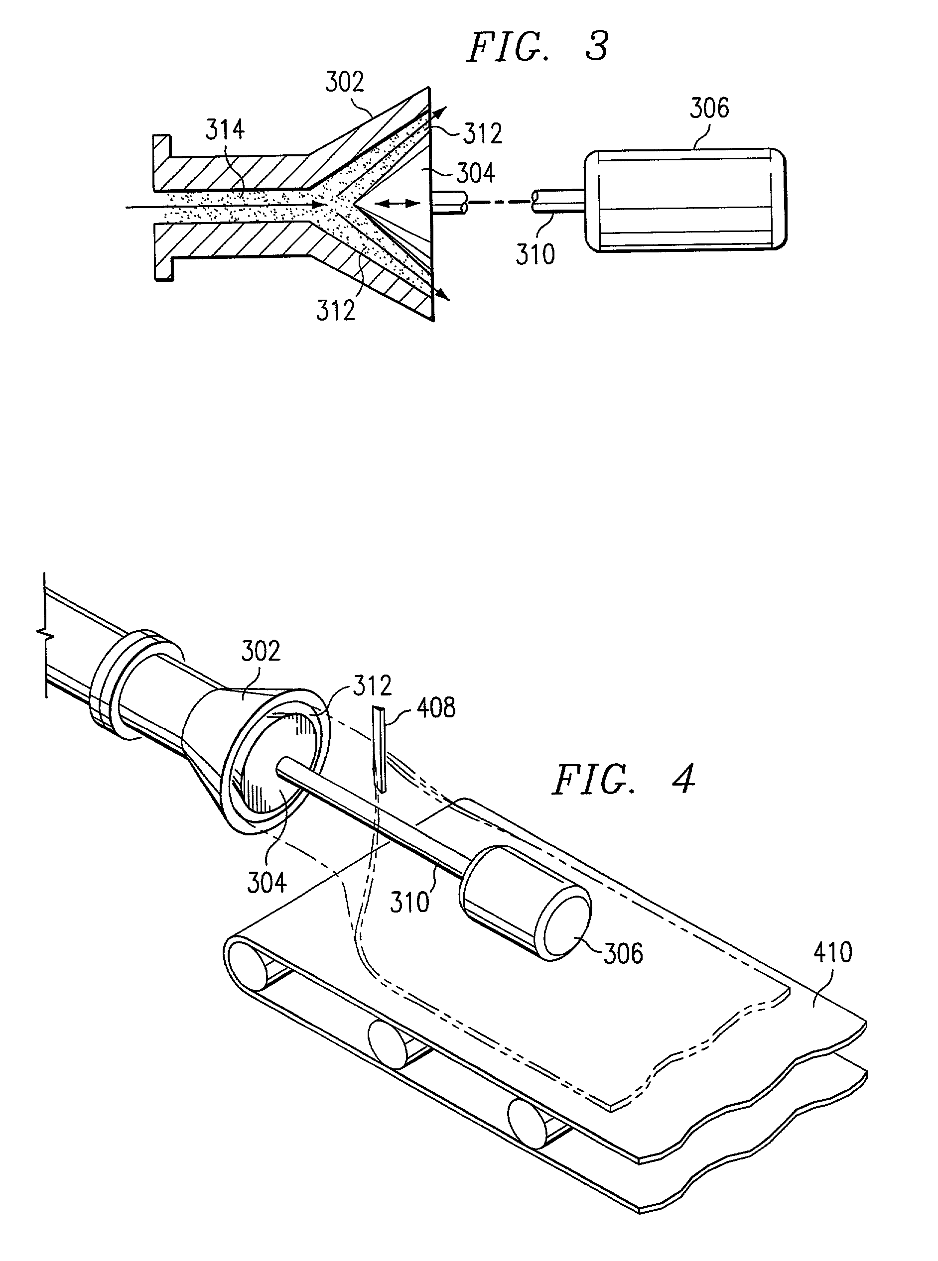
[0024]FIG. 3 illustrates a schematic presentation of one embodiment of the present invention. The die assembly of the present invention comprises an outer die or component 302, with a generally conically shaped opening or exit port connected via attachment means to an extruder assembly (not shown), and the inner cone 304 nested in non-contact with the outer die 302, having its own support and drive assembly 306 outside the extruder. The die 302 and the cone 304 are positioned to form an annular channel 312. The outer die 302 is in fluid communication with an extruder by means commonly known in the art. Dough 314 is forced into the outer die 302, contacts the inner cone 304, and proceeds between the outer die 302 and inner cone 304 to the exit channel 312. Pressure and dwell time for the extrudate is equal around the circumference of the exit 312.

[0025]The inner cone 304 is connected to a support assembly via a shaft 310 and is capable of clockwise and counter-clockwise axial rotatio...


PUM

PropertyMeasurementUnit
Thicknessaaaaaaaaaa
Forceaaaaaaaaaa
Torqueaaaaaaaaaa

Abstract

A rotating circular die for mounting on an extruder. The die incorporates an inner component comprising a cone with support independent of the outer component and extruder, thereby permitting forward and backward adjustment of the inner component in relation to the outer component during actual processing. Independent support for the inner cone eliminates the sanitary and microbial concerns that are present when die assemblies are housed within the extruder. The inner cone is self-centering to provide extrudate of uniform thickness and capable of imparting rotational shearing stresses on the extrudate to provide for starch alignment. The rotation of the inner component considered with the positional adjustability produces uniform extrudate as well as minimizes production downtime by reducing clogging and backup risks and providing for easy clean up.

Description

BACKGROUND OF THE INVENTION[0001]1. Technical Field[0002]The present invention relates to a rotating circular die for producing an extruded food product and, in particular, to an improved extruder die assembly that incorporates an independently supported inner cone which can be easily adjusted during processing to vary the thickness of the extrudate and maintain extrudate uniformity.[0003]2. Description of the Related Art[0004]Extrusion devices used in the food industry introduce a dough into a device and convey it via, for example, a screw pump to an inlet where the substance is forced through an extruder die. The extruder die is employed to perform a variety of functions, including forming or shaping the extrudate, and compressing and reducing the cross sectional area of the extrudate.[0005]One example of a commonly employed extruder die is a die comprising a linear extrusion exit channel. In operation, the extrudate is forced through the extruder passageway and through the linear...

Claims


Application Information

Patent Timeline
IPC IPC(8): B29C47/20B29C47/24B29C47/22B29C35/02B29C35/00B29C35/16B29C47/78B29C47/86B29C69/00B29C48/325B29C48/33
CPCB29C47/22B29C47/24B29C35/02B29C35/16B29C47/0026B29C47/0057B29C47/0059B29C47/0066B29C47/86B29C2793/0063B29C48/865B29C48/10B29C48/0018B29C48/0019B29C48/0022B29C48/325B29C48/33B29C48/86B29C48/87B29C48/06
Inventor BAJEMA, RICK WENDELL
Owner FRITO LAY NORTH AMERICA INC
Why Eureka
Try Eureka