Gaseous oxygen resonance igniter

a gaseous oxygen and resonance technology, applied in the direction of burners, combustion types, combustion processes, etc., can solve the problems of unstable zones of elevated pressure within the tubes, investigate the application of the phenomenon to existing technology, and achieve the effect of high temperatur

Inactive Publication Date: 2005-11-22
UNITED TECH CORP +1
View PDF16 Cites 20 Cited by
  • Summary
  • Abstract
  • Description
  • Claims
  • Application Information

AI Technical Summary

Problems solved by technology

Reflected shocks from the end of the resonance cavity couple and reinforce the detached bow shock, interacting with the flow within the tube such that the successive cycles of shocks cause the formation of a series of unstable zones of elevated pressure within the tube.
All of this initial work was academic in nature, however, and did not investigate applications of the phenomena to existing technology.

Method used


Image

  • Gaseous oxygen resonance igniter
  • Gaseous oxygen resonance igniter
  • Gaseous oxygen resonance igniter

Examples


Embodiment Construction

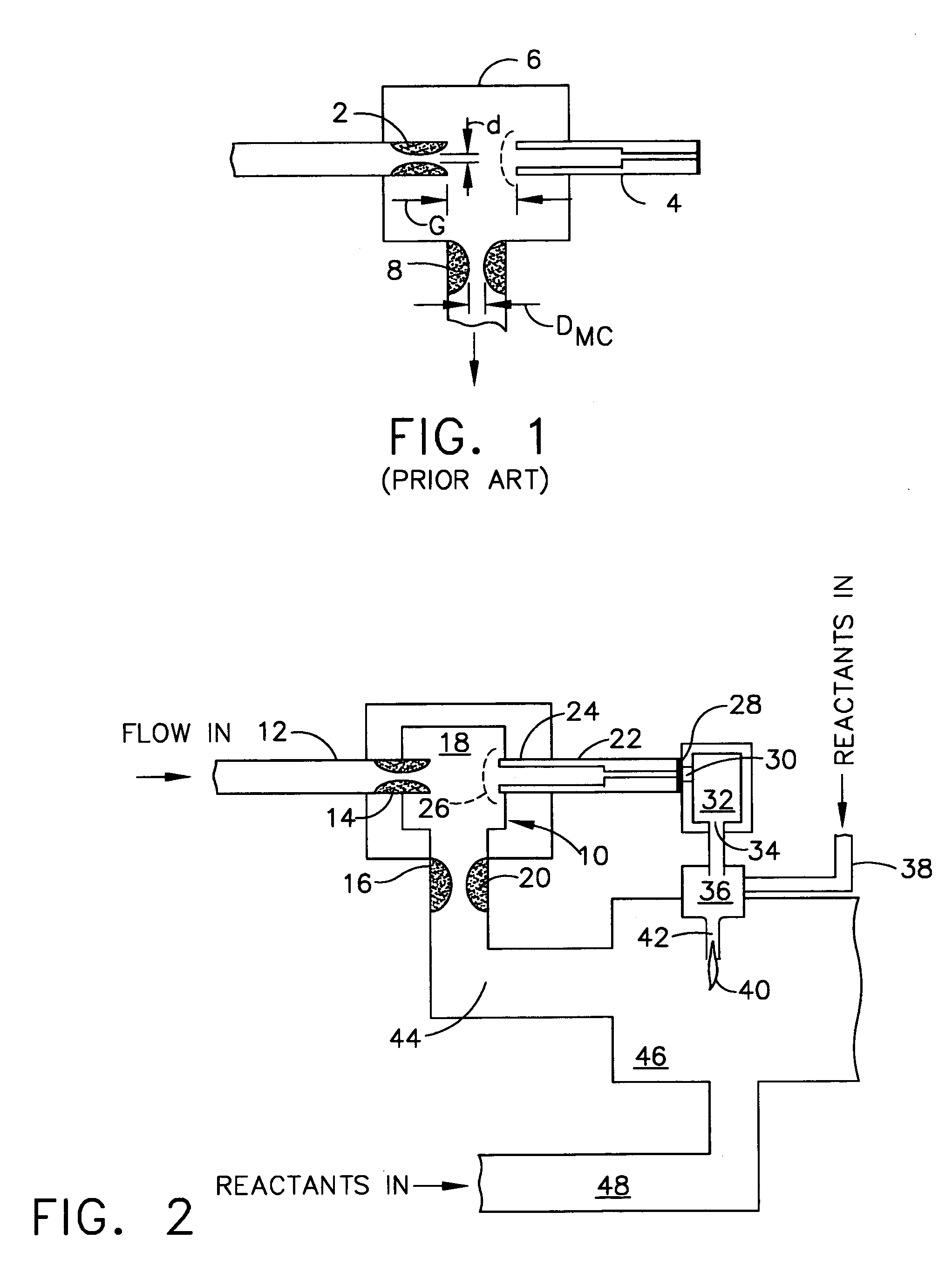
[0014]Referring to the drawings, FIG. 2 shows the basic arrangement of a resonance igniter employing the present invention. A body 10 has an oxygen inlet 12 incorporating a supersonic nozzle 14. An outlet 16 from the chamber 18 in the body employs an orifice 20 to maintain pressure in the body at a predetermined level, as will be described in greater detail subsequently. A resonance cavity 22 is engaged within an aperture 24 in the body opposite the inlet. Oxygen entering through the supersonic nozzle as underexpanded flow is axially directed at the resonance cavity, causing an oscillating detached bow shock 26 to form upstream of the entrance. Reflected shocks from the end of the resonance cavity couple and reinforce the detached bow shock, interacting with the flow within the resonance cavity such that the successive cycles of shocks cause the formation of a series of unstable zones of elevated pressure within the resonance cavity. These zones can produce temperature increases up ...


PUM


Abstract

A gaseous oxygen resonance igniter includes a body with a first inlet for gaseous oxygen incorporating a supersonic nozzle. An outlet from the body incorporates an orifice of predetermined size to maintain a desired pressure in the body. An aperture in the body opposite the first inlet provides a port to a ceramic resonance cavity. A ceramic bleed disc is engaged at a second end of the resonance cavity. An end cap incorporates a plenum adapted to receive high temperature oxygen flow from the resonance cavity through the bleed disc. An exhaust port is connected to the plenum for the high temperature oxygen which flows to a mixing chamber which introduces pilot fuel for ignition as a combustion initiation torch.

Description

BACKGROUND OF THE INVENTION[0001]1. Field of the Invention[0002]This invention relates generally to the field of resonance heating of gas for propellant and oxidizer ignition and, more particularly, to a system for resonance heating of oxygen employing a ceramic resonance cavity and hot gas bleed withdrawal for generating an ignition torch.[0003]2. Description of the Related Art[0004]Resonance ignition is based on a phenomenon known as gasdynamic resonance, wherein supersonic, underexpanded flow is axially directed from a supersonic nozzle 2 at a tube with a closed end, referred to as a resonance cavity 4, causing an oscillating detached bow shock to form in a chamber 6 upstream of the entrance to the cavity as shown in FIG. 1. Gas then exits the chamber through a restricting orifice 8. Reflected shocks from the end of the resonance cavity couple and reinforce the detached bow shock, interacting with the flow within the tube such that the successive cycles of shocks cause the format...

Claims


Application Information

Patent Timeline
Patent Type & Authority Patents(United States)
IPC IPC(8): F23Q13/00F23Q9/00
CPCF23Q13/00
Inventor ELVANDER, JOSHUA E.FISHER, STEVEN C.MIYATA, SHINJIRO
Owner UNITED TECH CORP
Why Eureka
Try Eureka