Lockable electrical plug and socket connection

a plug and socket connection, lockable technology, applied in the direction of coupling device connection, coupling prevention, coupling/disengagement of coupling parts, etc., can solve the problem of limiting the ability to cluster several plug and socket connections or other elements next to each other, unlocking and disconnecting the connection arrangement, and reducing the required installation space of the electrical connection arrangemen

Inactive Publication Date: 2005-11-22
AIRBUS OPERATIONS GMBH
View PDF22 Cites 3 Cited by
  • Summary
  • Abstract
  • Description
  • Claims
  • Application Information

AI Technical Summary

Benefits of technology

[0011]With the above described arrangement including the unlocking bail, the invention achieves a substantial advantage of avoiding the need of a lateral clear space to allow finger access to the flexible arms for unlocking the locking snap hooks. Instead, the unlocking bail simply needs to be pivoted with one finger, e.g. from the front face of the socket or second connector, and the bail in turn applies the necessary lateral pressure onto the flexible arms so as to deflect the arms and thereby unlock or release the locking snap hooks from the locking receivers. Thus, the invention achieves a significant reduction of the required installation space of the electrical connection arrangement, while still making it possible to unlock and disconnect the connection arrangement by hand in a simple manner.

Problems solved by technology

While the conventional construction of such a locking mechanism using locking snap hooks on flexible arms is relatively simple and economical in its construction and in its utilization, it unfortunately requires a certain free access space on both sides of the locking snap hooks to make it possible to apply the required finger pressure to the flexible arms or snap hooks for unlocking the same.
In many installations, it is not possible to provide such a clear lateral access space at the sides of the connection arrangement, and in any event, this limits the ability to cluster several plug and socket connections or other elements next to one another.

Method used


Image

  • Lockable electrical plug and socket connection
  • Lockable electrical plug and socket connection
  • Lockable electrical plug and socket connection

Examples


Embodiment Construction

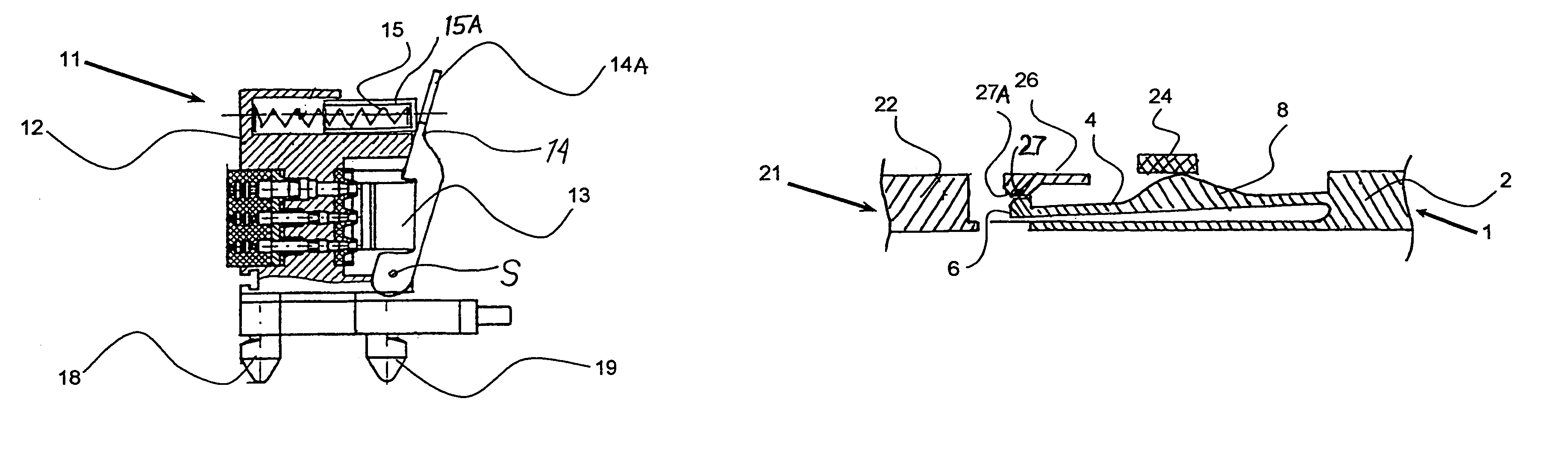
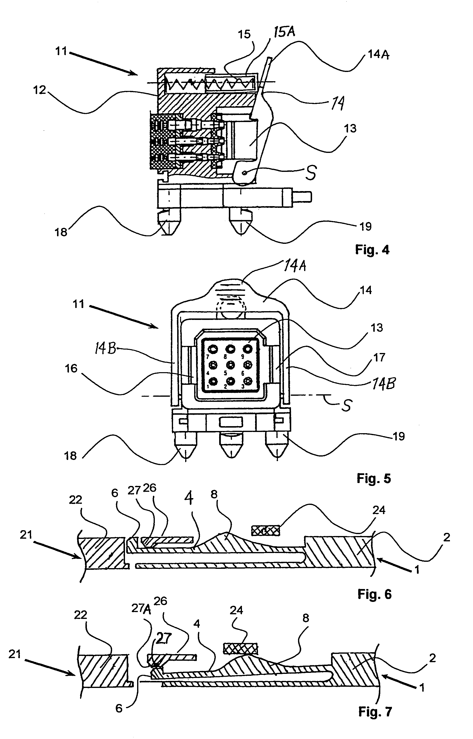
[0020]The inventive electrical connection arrangement includes a first connector and a second connector that can be selectively connected and locked as well as unlocked and disconnected from each other. In the present example embodiment, the first connector is represented by a connector plug 1 while the second connector is represented by a counter-plug or connector socket 11, whereby the plug 1 and socket 11 are configured to be selectively plugged together while establishing an electrical and mechanical connection therebetween.

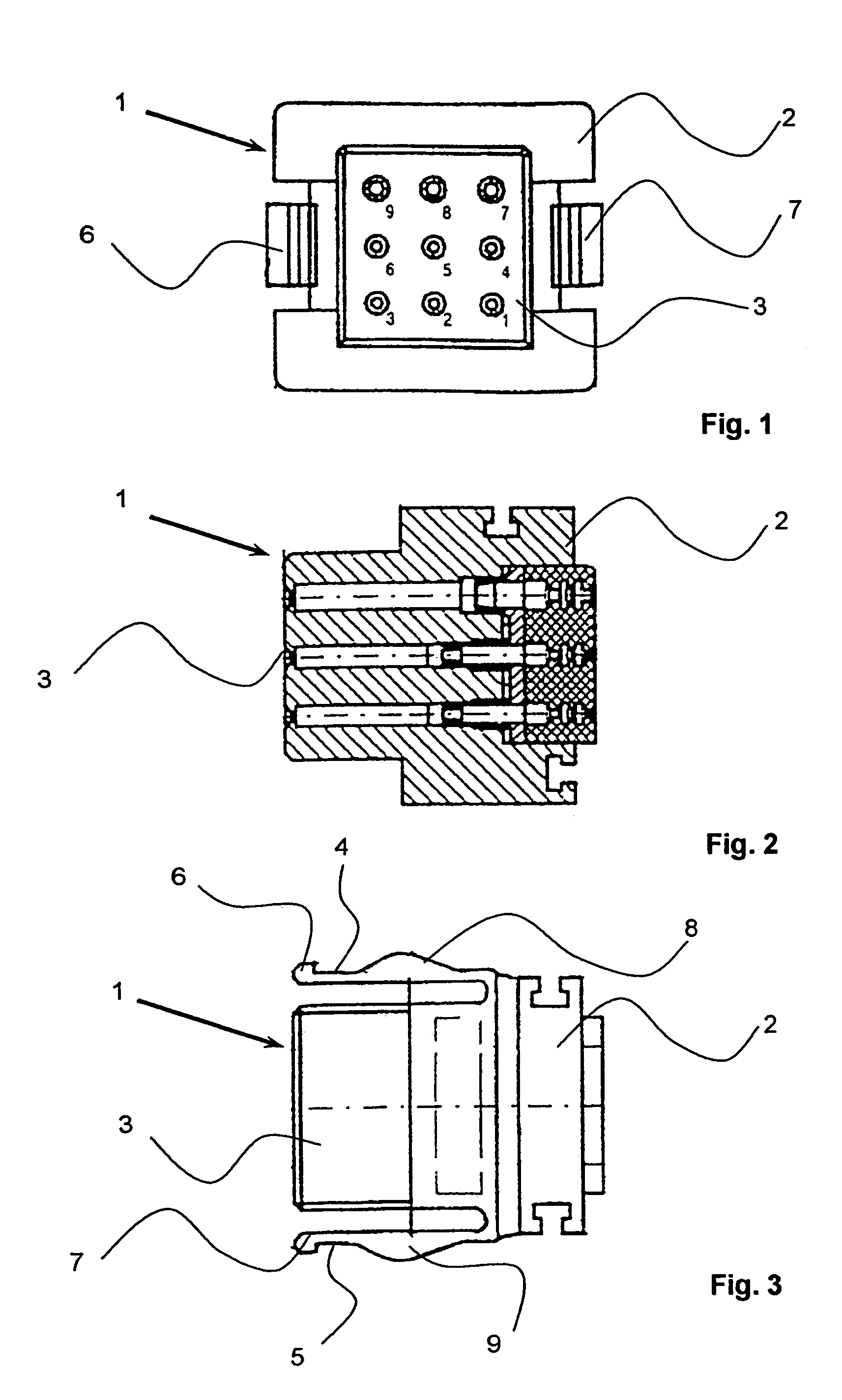
[0021]The connector plug 1 is shown in a front view, a vertical sectional view, and a top view, respectively in FIGS. 1, 2 and 3. The connector plug 1 includes an electrical contact arrangement 3 having a total of nine electrical contact pins received in an insulating housing 2. Particularly, the contact pins of the electrical contact arrangement 3 extend from front to back through the housing 2, as can be seen in the sectional view of FIG. 2. As can be seen ...


PUM


Abstract

An electrical plug has locking hooks on the ends of flexible arms extending from its housing. An electrical socket has locking receivers on its housing. When the plug is connected with the socket, the locking hooks engage the locking receivers to form a locked connection. A spring-loaded unlocking bail is pivotally arranged on the housing of the socket. Finger pressure applied to the bail against the spring bias pivots the bail so that its bail legs pivot over and press against protrusions of the flexible arms, to inwardly deflect the arms and disengage the locking hooks from the locking receivers, thereby unlocking the arrangement so that the plug can be separated from the socket.

Description

PRIORITY CLAIM[0001]This application is based on and claims the priority under 35 U.S.C. §119 of German Patent Application 103 44 955.8, filed on Sep. 27, 2003, the entire disclosure of which is incorporated herein by reference.FIELD OF THE INVENTION[0002]The invention relates to a lockable electrical connection established by an electrical plug and an electrical counter-plug or socket that can be selectively plugged together and locked.BACKGROUND INFORMATION[0003]It is generally known to provide an electrical connector plug and socket combination that can be plugged together and then mechanically locked to prevent an inadvertent disconnection or loosening thereof. For example, it is known to provide flexible arms having locking hooks or “snap hooks” on the ends thereof, on a housing of the connector plug, and to provide locking receivers or counter-recesses on the housing of the counter-plug or socket. When the plug and socket are plugged together, the locking hooks snap and engage...

Claims


Application Information

Patent Timeline
Patent Type & Authority Patents(United States)
IPC IPC(8): H01R13/633H01R13/635H01R13/627
CPCH01R13/6273H01R13/635
Inventor ROESE, FRANK
Owner AIRBUS OPERATIONS GMBH
Why Eureka
Try Eureka