Electronic endoscope system with color-balance alteration process

a color-balance alteration and endoscope technology, applied in the field of electronic endoscope systems, can solve the problems of troublesome development of harmless dyes, difficult to examine the subtle unevenness of mucous membrane surfaces, and medical examination methods with dyes

Inactive Publication Date: 2005-11-22
ASAHI KOGAKU KOGYO KK
View PDF10 Cites 119 Cited by
  • Summary
  • Abstract
  • Description
  • Claims
  • Application Information

AI Technical Summary

Benefits of technology

[0015]Therefore, an object of the present invention is to provide an electronic endoscope system with a color-balance alteration process, in which the color-bal

Problems solved by technology

In particular, the mucous membrane surface of the stomach or the colon features a reddish orange tone as a whole, and thus it is very difficult to examine the subtle unevenness of the mucous membrane surface.
However, there are various drawbacks in the dye-spraying medical examination method.
For example, a dye must be harmless to a human body, and it is troublesome to develop a harmless dye.
Also, an introduction of a dye-spraying medical examination method prolongs the medical examination time when using the electronic endoscope system, resulting in an increase in the patient's pain.
Further, once a dye-solution is sprayed, it is impossible to immediately reproduce an endoscope image without the sprayed dye-solution.
In this case, for example, when the spatial frequency of the captured unevenness image is too low in comparison with the pixel pitch of the image sensor, it is impossible to prop

Method used


Image

  • Electronic endoscope system with color-balance alteration process
  • Electronic endoscope system with color-balance alteration process
  • Electronic endoscope system with color-balance alteration process

Examples


first embodiment

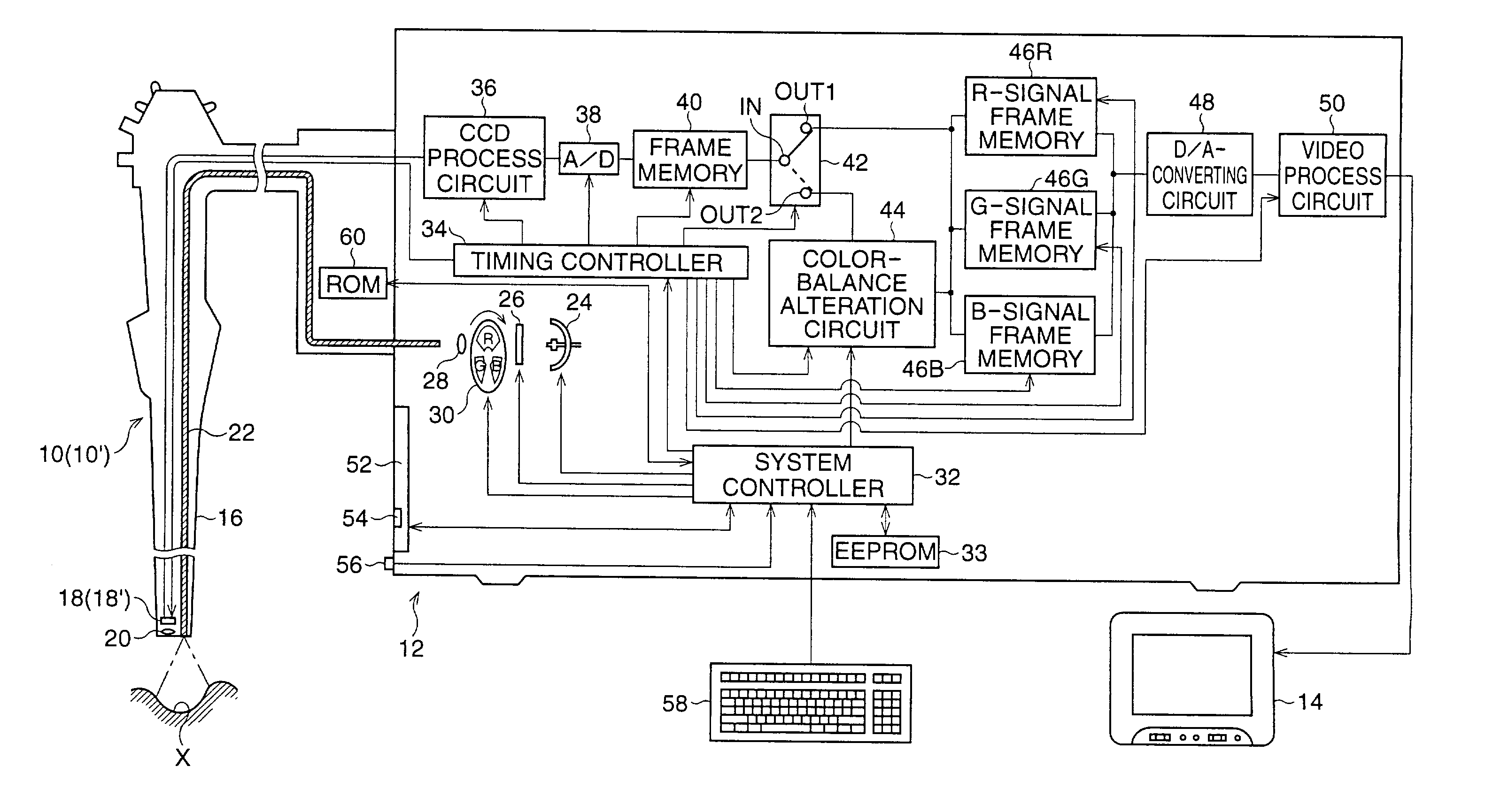
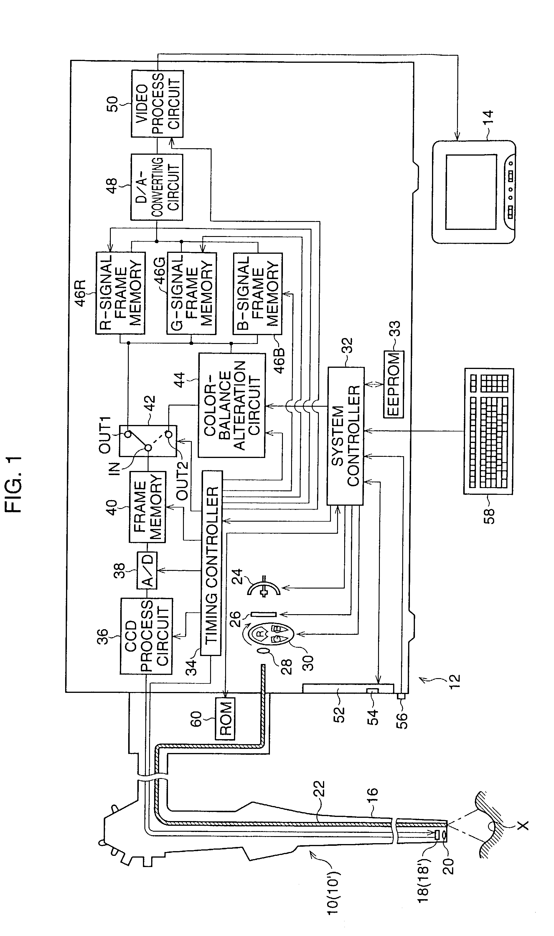
[0054]Referring to FIG. 1, an electronic endoscope system according to the present invention is shown as a block diagram. The electronic endoscope system comprises a video scope 10, an image-signal processing unit 12 to which the video scope 10 is detachably coupled, and a TV monitor 14 to which the image-signal processing unit 12 is connected.

[0055]The video scope 10 is representative of various types of scopes, used for bronchial, esophageal, gastro, colon, etc. medical examinations. Namely, at least two different types of video scopes use the image-signal-processing unit 12 in common. This is because the scope 10 is detachably coupled to the image-signal processing unit 12.

[0056]The video scope 10 includes a flexible conduit 16 which is provided with a solid-state image sensor 18, such as a CCD (charge-coupled-device) image sensor, at the distal end thereof, and the CCD image sensor 18 is associated with an objective lens 20. When the connection is established between the video s...

second embodiment

[0179]Referring to FIG. 26, an electronic endoscope system according to the present invention is shown as a block diagram. In this drawing, the features similar to those of FIG. 1 are indicated by the same references.

[0180]In the second embodiment, an on-chip color filter method is introduced to reproduce an endoscope image as a full color image on a TV monitor 14. Namely, two types of video scopes 10 and 10′ are respectively provided with CCD image sensors 18 and 18′, each of which has a complementary color filter provided on a light-receiving surface thereof. Note, similar to the first embodiment, the CCD image sensor 18 features m×n image-pixel signals, and the CCD image sensor 18′ features M×N image-pixel signals (M>m, N>n).

[0181]In the second embodiment, an image-signal processing unit 12 is constituted so as to conform to the on-chip color filter method as discussed hereinafter.

[0182]First, a light source device, provided in the image-signal processing unit 12, is formed by a ...

third embodiment

[0214]Referring to FIG. 29, an electronic endoscope system according to the present invention is shown as a block diagram. The third embodiment is essentially identical to the first embodiment except that the electronic zooming system is eliminated from the image-signal processor provided in the image-signal processing unit 12. In this drawing, the features similar to those of FIG. 1 are indicated by the same references.

[0215]In general, in an electronic endoscope system, an objective lens system, used in a video scope, features a large depth of focus, because a close-range object image and / or a distant-range object image to be captured by a CCD image sensor must be focused on a light-receiving surface of the CCD image sensor by the objective lens system, before the captured close-range object image and / or distant-range object image can be sharply reproduced on a TV monitor.

[0216]In this case, to maintain a constant overall luminance of a reproduced object image or endoscope image o...


PUM


Abstract

An electronic endoscope system includes a video scope having a solid-state image sensor for successively producing a frame of color image-pixel signals, and an image-signal processor for producing a color video signal based on the frame of color image-pixel signals. A calculation system calculates a difference value between a value of a central single-color image-pixel signal and an average of values of one selected from single-color image-pixel signals surrounding the central single-color image-pixel signal. A color-balance alteration system alters the value of the central single-color image-pixel signal based on the difference value calculated by the calculation system. A selection system performs the selection of the circumferential image-pixel signals such that the circumferential image-pixel signals to be selected are farther from the central image-pixel signal, as a spatial frequency of an endoscope image to be reproduced based on the color video signals is lower.

Description

BACKGROUND OF THE INVENTION[0001]1. Field of the Invention[0002]The present invention relates to an electronic endoscope system in which an endoscope image is reproduced as a full color image on a TV monitor, and, in particular, to such an electronic endoscope system with a simulated dye-spraying process or color-balance alteration process, which is constituted such that the endoscope image can be reproduced on the TV monitor as if it were sprayed with a dye-solution.[0003]2. Description of the Related Art[0004]As is well known, an electronic endoscope system includes a video scope, inserted in an organ of a human body, having a solid-state image sensor for capturing an organ image or endoscope image as a frame of image-pixel signals, an image-signal processing unit for producing a video signal based on the frames of image-pixel signals successively read from the solid-state image sensor, and a TV monitor for reproducing the endoscope image as a motion picture based on the video sig...

Claims


Application Information

Patent Timeline
IPC IPC(8): A61B1/04H04N9/73G06T1/00H04N1/393H04N1/48H04N5/225H04N5/335H04N5/378H04N9/04
CPCA61B1/0638H04N9/735A61B1/00009H04N23/88
Inventor OZAWA, RYOKIMISHIMA, MIKIHITO
Owner ASAHI KOGAKU KOGYO KK
Why Eureka
Try Eureka