Compact packaging of multiple fiber lasers

a technology of fiber lasers and compact packaging, applied in the field of fiber packaging, can solve the problems of limited size, large volume inside the spool, and generally circular shape of the spool, and achieve the effect of small volum

Inactive Publication Date: 2005-11-22
NORTHROP GRUMMAN SYST CORP
View PDF4 Cites 20 Cited by
  • Summary
  • Abstract
  • Description
  • Claims
  • Application Information

AI Technical Summary

Benefits of technology

[0006]In one preferred form, the present invention provides a compact fiber packaging system comprising spools in increasing sizes nested around one another, wherein the fibers are wrapped around an inner spool that is nested inside at least one outer spool, and the fibers are further wrapped around the outer spool to form a module. Accordingly, the volume inside the outer spool is efficiently filled with the inner spool and the fibers wrapped around the inner spool, thereby allowing a larger number of fibers to be packaged into a relatively small volume.
[0008]In addition to efficiently utilizing volume by nesting the spools, the packaging system of the present invention also utilizes the volume inside the inner spool. The inner spool, as with other spools, defines a hollow center that comprises a volume. The volume of the hollow center is accordingly filled with equipment and materials that are required for operation of the fibers. Furthermore, since the shape of the spools is not necessarily round, and is instead primarily limited by the minimum bend radius of the fibers, a wide variety of equipment and materials may be disposed within the hollow center. Moreover, the shape of the hollow center may be designed for a specific set of fiber equipment to more efficiently utilize the available volume.
[0010]The compact fiber packaging system of the present invention further provides devices and methods for dissipating heat generated by the laser fibers in order to minimize power losses. In one form, phase change materials are disposed within the modules, local to, for example, pump diodes to store waste heat that is generated by the laser fibers during operation. The phase change materials absorb waste heat, and then a relatively small, light weight, and less expensive cooling system is employed to remove the waste heat. The phase change materials may be disposed on the shelf or within the hollow center of the inner spool, depending on the location of the heat source(s) and the particular application.
[0011]Additional devices and methods are provided to minimize thermal gradients within the fibers to further minimize power losses. In one form, an insulating layer is disposed within the fibers and each spool. Additionally, a thermally conductive potting compound may be disposed between the spools to further minimize thermal gradients. Yet another method of reducing thermal gradients involves using a thermally conductive material in the structure, or mandrels, of the spools. Either one or a plurality of the aforementioned devices and methods may be employed according to the present invention to minimize thermal gradients between the fibers.

Problems solved by technology

Further, the spools are generally circular in shape and are limited in size by the minimum bend radius of the fiber lasers.
Unfortunately, the individually wrapped spools of the known art cannot be used in systems that require a large number of fibers in a limited amount of space due to the excessive amount of volume consumed by the spools.
Additionally, the volume inside the spool often goes unused, which further reduces the volume efficiency of the spools.
For example, laser systems for weapons applications in military aircraft must be capable of being packaged within avionics or weapons bays, which are further limited by the size of access doors.
In addition to limited volume requirements, high power laser systems further require control of temperature and thermal gradients within the fibers to minimize laser power losses.
High power fiber lasers generate a significant amount of heat that must be removed from the system.
Unfortunately, the continuous duty cooling systems are relatively large and expensive and run continuously to remove the waste heat from the fiber lasers, although the fiber lasers often only operate intermittently.

Method used


Image

  • Compact packaging of multiple fiber lasers
  • Compact packaging of multiple fiber lasers
  • Compact packaging of multiple fiber lasers

Examples


Embodiment Construction

[0019]The following description of the preferred embodiments is merely exemplary in nature and is in no way intended to limit the invention, its application, or uses.

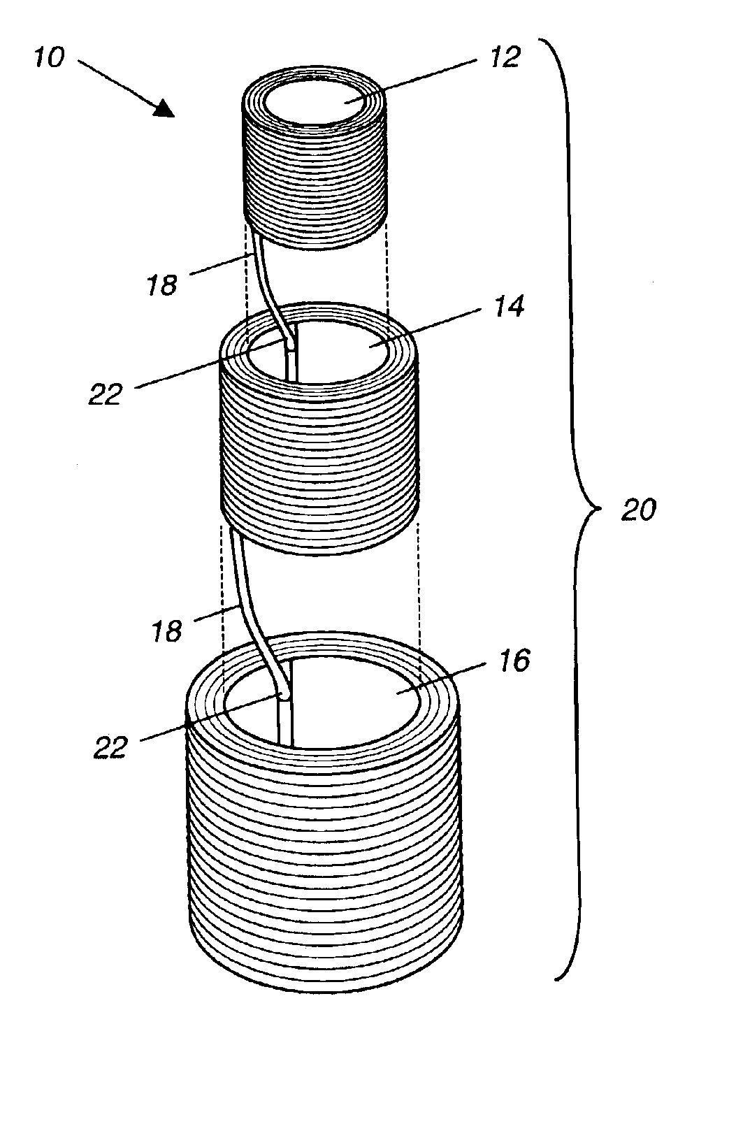
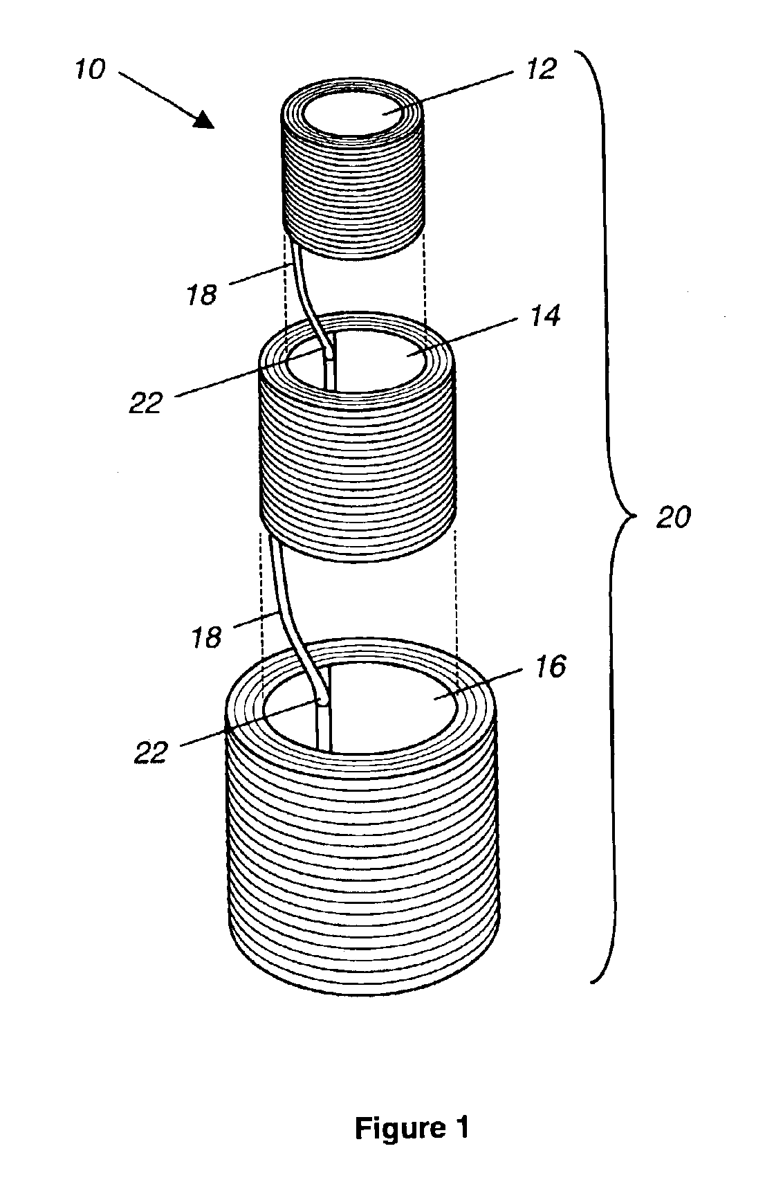
[0020]Referring to FIG. 1, the compact fiber packaging system of the present invention is illustrated and generally indicated as reference numeral 10. The compact fiber packaging system 10 generally comprises an inner spool 12 nested inside a first outer spool 14, which is nested inside a second outer spool 16. As shown, the outer diameter of inner spool 12 is slightly smaller than the inner diameter of first outer spool 14, and similarly, the outer diameter of first outer spool 14 is slightly smaller than the inner diameter of second outer spool 16. Accordingly, the spools may be nested inside one another for efficient volume utilization.

[0021]As shown, the fibers 18 are wrapped around the inner spool 12 and then successively around the first outer spool 14 and then the second outer spool 16 to form a module 20, wherei...


PUM


Abstract

A compact fiber packaging system for fiber lasers is provided that comprises a series of spools nested inside one another for efficient volume utilization. The spools comprise an inner spool nested inside at least one outer spool to form a module. Generally, the fiber lasers are wrapped around the inner spool, and then around successive outer spools as required to form the module. Furthermore, the modules may be stacked to form a fiber assembly. The compact fiber packaging system further comprises devices and methods for minimizing thermal gradients between fibers and for removing Waste heat from the system. Additionally, the available volume is further utilized by disposing equipment and materials for operation of the fibers inside a hollow center defined by the inner spool, between the nested spools, and adjacent the nested spools.

Description

BACKGROUND OF THE INVENTION[0001]The present invention relates generally to the packaging of fibers, and more particularly to compact packaging of high power fiber lasers that further require controlled thermal gradients and removal of waste heat.[0002]Fiber lasers of the known art are generally packaged by wrapping the fiber lasers around individual spools. The individual spools are commonly the same size and are placed side by side, or adjacent one another for packaging. Further, the spools are generally circular in shape and are limited in size by the minimum bend radius of the fiber lasers. Unfortunately, the individually wrapped spools of the known art cannot be used in systems that require a large number of fibers in a limited amount of space due to the excessive amount of volume consumed by the spools. Additionally, the volume inside the spool often goes unused, which further reduces the volume efficiency of the spools.[0003]Laser systems comprising hundreds to thousands of f...

Claims


Application Information

Patent Timeline
Patent Type & Authority Patents(United States)
IPC IPC(8): B65D85/66B65H75/20B65H75/18G02B6/00G02B6/44H01S3/067
CPCH01S3/06704G02B6/4457H01S3/06758
Inventor ZAMEL, JAMES M.KOMINE, HIROSHI
Owner NORTHROP GRUMMAN SYST CORP
Why Eureka
Try Eureka