Radio base station apparatus and radio communication method

a radio communication and base station technology, applied in multiplex communication, polarisation/directional diversity, wireless communication services, etc., can solve the problem that corresponding to n channels will require an amount of processing corresponding to (n direction patterns)m, and achieve the effect of improving the reception characteristic and increasing the system capacity

Inactive Publication Date: 2005-11-22
PANASONIC CORP
View PDF18 Cites 8 Cited by
  • Summary
  • Abstract
  • Description
  • Claims
  • Application Information

AI Technical Summary

Benefits of technology

[0007]It is an object of the present invention to provide a radio base station apparatus and radio communication method capable of improving reception characteristics of uplink signals and increasing the system capacity by combining an AAA and an interference canceller without increasing the hardware scale.
[0011]The present inventor has come up with the present invention focused on group directivity reception with respect to a combination of the above-described AAA technology and an interference canceller. That is, a main point of the present invention is to generate a reference signal from a signal after elimination of interference, perform group directivity control using a difference between the reference signal and the post-AAA reception signal as an error signal and thereby provide a temporal / spatial interference canceller suited to a CDMA system, improve the reception characteristic and increase the system capacity.

Problems solved by technology

However, if each channel receives signals using an AAA individually, an individual MUD is required according to each directivity, and if the amount of processing of the MUD corresponding to one AAA reception signal (that eliminates interference corresponding to N channels) is assumed to be M, then there is a problem that AAA reception corresponding to N channels will require an amount of processing corresponding to (N direction patterns)×M.

Method used


Image

  • Radio base station apparatus and radio communication method
  • Radio base station apparatus and radio communication method
  • Radio base station apparatus and radio communication method

Examples


embodiment 1

(Embodiment 1)

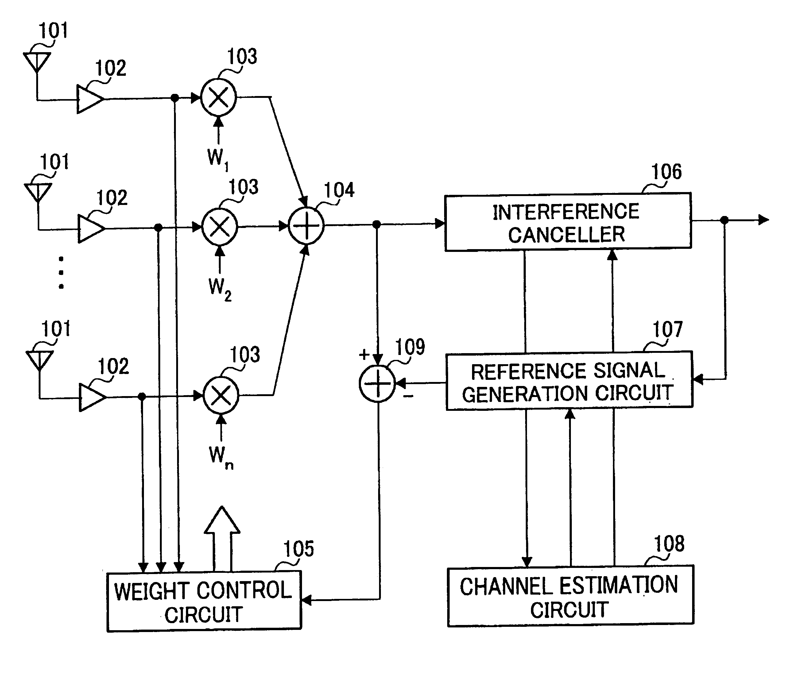
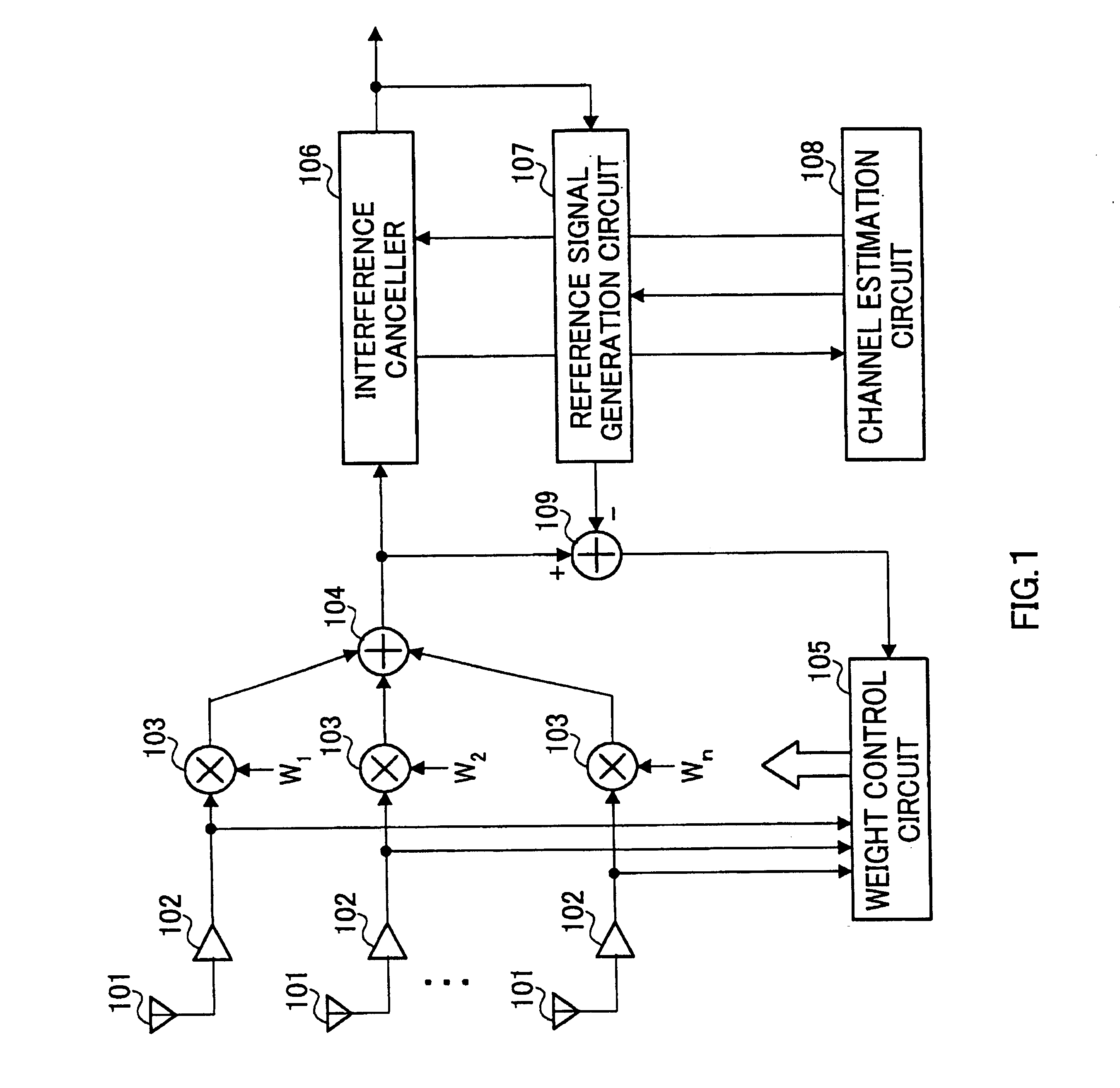
[0021]FIG. 1 is a block diagram showing a configuration of a radio base station apparatus according to Embodiment 1 of the present invention. The radio base station apparatus according to this embodiment carries out group directivity control using a signal subjected to interference canceller processing as a reference signal and using a difference between the reference signal and the post-AAA reception signal as an error signal.

[0022]A signal received through antenna 101 is subjected to predetermined radio reception processing (down-conversion and A / D conversion, etc.) and converted to a baseband signal at radio reception processing section 102. This received data (baseband signal) is sent to weight control circuit 105 and multiplier 103 at the same time.

[0023]Weight control circuit 105 estimates the direction of arrival from the received data and carries out reception weights corresponding to the received data using the result of the direction of arrival estimation. Th...

embodiment 3

(Embodiment 3)

[0054]This embodiment describes a modification example of the radio base station apparatus of the present invention. FIG. 4 is a block diagram showing a configuration of a radio base station apparatus according to Embodiment 3 of the present invention. In FIG. 4, the same parts as those in FIG. 1 are assigned the same reference numerals as those in FIG. 1 and detailed explanations thereof will be omitted.

[0055]First, a modification example of replica signal generation will be explained. The following three methods are available to generate a replica signal:

[0056](1) Using only known signal after interference cancellation processing (e.g., pilot signal)

[0057](2) Using provisional decision signal of information data in addition to pilot signal

[0058](3) Using output of error correction(FEC) / decoding circuit 401 or decision data (after deinterleave+error correction(FEC) / decoding in general) when information data section is used

[0059]In this method, a control delay increase...

embodiment 4

(Embodiment 4)

[0073]FIG. 6 is a block diagram showing a configuration of a radio base station apparatus according to Embodiment 4 of the present invention. In FIG. 6, the same parts as those in FIG. 1 are assigned the same reference numerals and detailed explanations thereof will be omitted.

[0074]This embodiment describes a radio base station apparatus that uses a signal subjected to interference canceller processing and then error correction(FEC) / decoding as a reference signal and carries out group directivity control using a difference between the reference signal and a post-AAA reception signal as an error signal.

[0075]The operations after the signal from the communication terminal is AAA received by antenna 101 until the signal is subjected to interference cancellation processing at interference canceller 106 are the same as that in Embodiment 1.

[0076]The demodulated data subjected to interference canceller processing is sent to de-interleaving circuit 601, deinterleaved there a...


PUM


Abstract

Focused on group directivity reception with respect to a combination between an adaptive array antenna technology and an interference canceller, the present invention is intended to improve the reception characteristic and improve the system capacity by generating a reference signal from the signal after interference elimination, using a difference between the reference signal and the signal after adaptive array antenna reception as an error signal and carrying out group directivity control.

Description

TECHNICAL FIELD[0001]The present invention relates to a radio base station apparatus and radio communication method in a digital radio communication, and more particularly, to a radio base station apparatus and radio communication method capable of improving reception characteristics of uplink signals and increasing the system capacity in a DS-CDMA (Direct Sequence-Code Division Multiple Access) system.BACKGROUND ART[0002]In digital radio communications, an adaptive array antenna (hereinafter referred to as “AAA”) technology is used which controls directivities adaptively by adding weights to antenna outputs from a plurality of antenna elements. This AAA technology can suppress interference signals taking advantage that signals arrive from different directions and controlling directivities adaptively. Thus, the adaptive array antenna technology is an ideal method for eliminating interference signals on a same channel.[0003]On the other hand, in digital radio communications, an inter...

Claims


Application Information

Patent Timeline
Patent Type & Authority Patents(United States)
IPC IPC(8): H01Q3/26H04B1/10H04B1/7107H04B7/08H04B7/10H04B7/26H04J13/00H04W16/28H04W88/08H04W88/14
CPCH01Q3/2617H04B7/0848H04B7/08H04B7/155H04W88/08
Inventor MIYA, KAZUYUKI
Owner PANASONIC CORP
Why Eureka
Try Eureka