Exhaust emission control apparatus for internal combustion engine

a technology of exhaust emission control and internal combustion engine, which is applied in the direction of electrical control, process and machine control, instruments, etc., can solve the problems of inability to increase the exhaust pressure, malfunction of the exhaust valve, and unburned substances such as hc, so as to reduce the harmful substances in the exhaust, reduce the cost, and detect the effect of harmful substances

Inactive Publication Date: 2005-11-29
MITSUBISHI MOTORS CORP
View PDF7 Cites 61 Cited by
  • Summary
  • Abstract
  • Description
  • Claims
  • Application Information

AI Technical Summary

Benefits of technology

[0017]It is therefore an object of the present invention to provide an exhaust emission control apparatus for an internal combustion engine, which is capable of reliably detecting a failure of an exhaust flow control device, which suppresses the flow of exhaust so as to sufficiently reduce harmful substances in exhaust, at a low cost.

Problems solved by technology

This exhaust emission control technique, however, has the problem that unburned substances such as HC are emitted into the atmosphere during the period until the catalyst is activated.
This is a serious problem because the amount of harmful substances emitted into the atmosphere during the period until the catalyst is activated reaches about 90% of the total emission in a cold mode.
Incidentally, since the above-mentioned sealed type variable exhaust valve is subjected to high temperatures and high pressures, it may break down if used for a long period of time, causing malfunction of its valve.
The malfunction of the valve of the sealed type variable exhaust causes the problem that the valve cannot close and therefore the exhaust pressure cannot be increased even when the exhaust pressure is required to be increased, or the valve is kept closed and therefore the exhaust pressure remains high even when the exhaust pressure is not required to be increased.
If the exhaust pressure cannot be increased, the harmful substances emitted until the activation of the catalyst may not be satisfactorily purified because the purification of exhaust emission is not promoted.
The exhaust pressure sensor is usually expensive because it must be configured to withstand high temperatures and high pressures, thus increasing the cost of parts.
Moreover, the exhaust pressure sensor itself may break down.
In this case, however, since the failure detecting accuracy of the sealed variable exhaust valve is greatly affected by the accuracy of the exhaust gas sensor, the failure detecting accuracy is lowered as the exhaust gas sensor deteriorates with age.
Moreover, as is the case with the exhaust pressure sensor, the exhaust gas sensor itself may break down.

Method used


Image

  • Exhaust emission control apparatus for internal combustion engine
  • Exhaust emission control apparatus for internal combustion engine
  • Exhaust emission control apparatus for internal combustion engine

Examples


first embodiment

[0073]First, a description will be given of a

[0074]FIG. 3 is a flow chart showing a failure diagnosis routine according to the first embodiment of the present invention, and the following description will be given with reference to the flow chart of FIG. 3.

[0075]In Step S10, it is determined whether an exhaust flow control mode is being executed or not. Specifically, it is determined whether the ECU 60 has outputted an instruction for starting the exhaust flow control. If the determination result is True (Yes), the process proceeds to Step S12.

[0076]It should be noted that the exhaust flow control is carried out on the assumption that the exhaust gas temperature increase control is provided by the two-stage combustion operation, the compression S / L operation, and so forth, and thus, the determination as to whether control is provided in the exhaust flow control mode or not includes a determination as to whether the exhaust gas temperature increase control is being provided or not. A...

second embodiment

[0099]A description will now be given of a

[0100]FIG. 4 is a flow chart showing a failure diagnosis routine according to the second embodiment of the present invention, and the following description will be given with reference to the flow chart of FIG. 4. Here, a description of parts and elements corresponding to those of the above described first embodiment is omitted, and a description of differences will only be given.

[0101]According to the second embodiment, it is determined in the Step S10 that the exhaust flow control mode is being executed, and in the Step S12, the throttle angle θth is fixed at the predetermined value θtha, the A / F is fixed at the predetermined value AFa, and the ignition timing is fixed at the predetermined value SAa. The process then proceeds to Step S14′.

[0102]In the Step S14′, a predetermined deviation ΔNe2 serving as a determination threshold for the engine speed Ne is set according to the following equation (2):

ΔNe2=(target pressure (mmHg) / 100 mmHg)×0....

third embodiment

[0115]A description will now be given of a

[0116]FIG. 5 is a flow chart showing a failure diagnosis routine according to the third embodiment of the present invention, and the following description will be given with reference to the flow chart of FIG. 5. Here, a description of parts and elements corresponding to those of the above described first embodiment is omitted, and only a description of differences will be given.

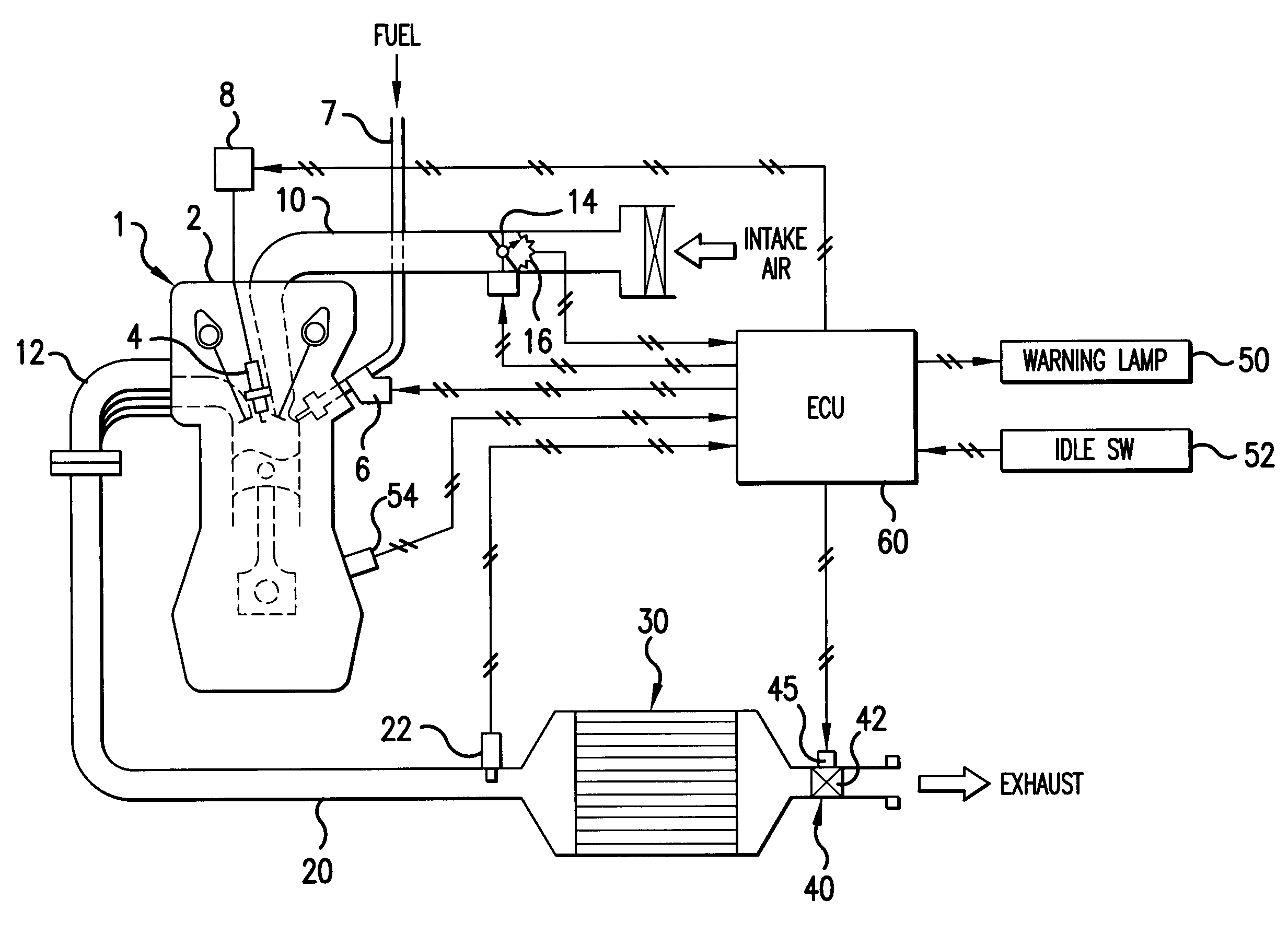
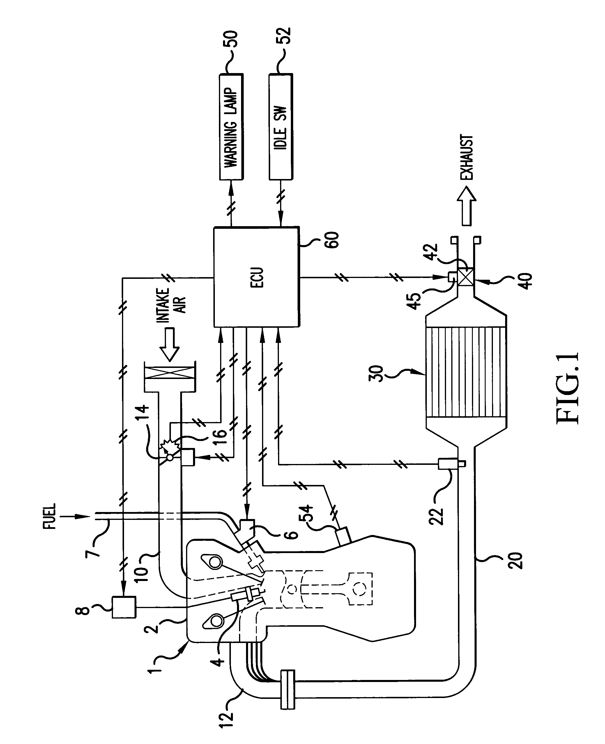
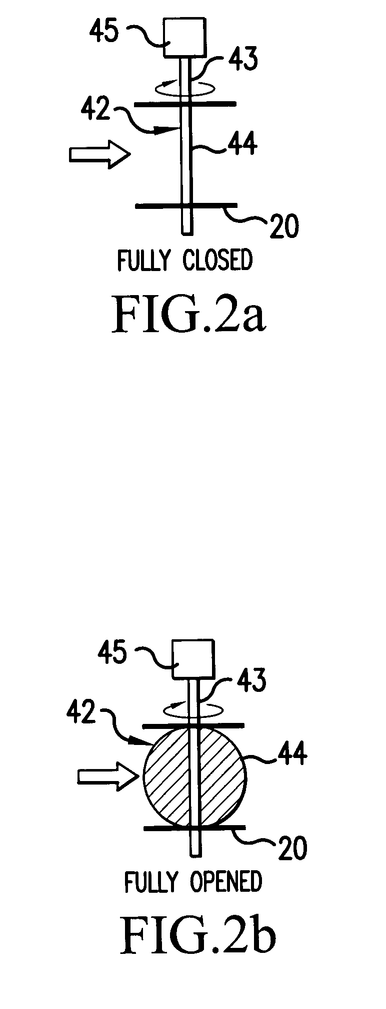
[0117]In the Step S16, the sealed type opening and closing valve 42 is controlled to a predetermined angle (for example, fully closed) to suppress the flow of exhaust. Then, in Step S18″, as described above, in the state in which the exhaust pressure has been increased with the throttle angle θth being fixed at the predetermined value θtha, the A / F being fixed at the predetermined value AFa, and the ignition timing being fixed at the predetermined value SAa, the present engine speed Ne (second parameter) is found based on information supplied from the crank angle sen...


PUM


Abstract

There is provided an exhaust emission control apparatus for an internal combustion engine, which includes a failure diagnostic device that fixes three parameters selected from the group consisting of the engine speed detected by an engine speed detecting device, the fuel quantity controlled by a fuel quantity control device, the ignition timing controlled by an ignition timing control device, and the intake air volume controlled by an intake air control device at respective predetermined values, and finds values of the remaining one parameter, and compares the values of the remaining one parameter with each other to determine whether an exhaust flow control apparatus has failed or not.

Description

CROSS-REFERENCE TO THE RELATED APPLICATION[0001]The application incorporates by reference the subject matter of Application No. 2002-72410 filed in Japan on Mar. 15, 2002, on which a priority claim is based on under 35 U.S.C. §119(a).BACKGROUND OF THE INVENTION[0002]1. Field of the Invention[0003]The present invention relates to a failure diagnosing technique for determining whether an exhaust flow control apparatus, which suppresses the flow of exhaust, has failed or not.[0004]2. Description of the Related Art[0005]Conventionally, an exhaust emission control technique utilizing the reaction on a catalyst has been known as a technique for reducing harmful substances (e.g., unburned substances such as HC, CO, and H2 as well as smoke, NOx, and so forth) in exhaust.[0006]This exhaust emission control technique, however, has the problem that unburned substances such as HC are emitted into the atmosphere during the period until the catalyst is activated. This is a serious problem because...

Claims


Application Information

Patent Timeline
Patent Type & Authority Patents(United States)
IPC IPC(8): F02D9/04F01N3/20F01N3/24F01N11/00F02D41/06F02D41/22F02D41/26F02D45/00
CPCF01N3/20F01N11/00F02D41/221F02D41/266F01N2260/14F01N2550/00F01N2570/10F01N2570/12F01N2570/14F02D9/04F02D41/1454F02D2200/0404Y02T10/47Y02T10/40F02D45/00
Inventor TAMURA, YASUKI
Owner MITSUBISHI MOTORS CORP
Why Eureka
Try Eureka