LED backlight module

a backlight module and led technology, applied in the field of led backlight modules, can solve the problems of inability to provide uniform illumination in the conventional backlight module b>1/b>, and the inability to easily ignite the cold cathode fluorescent lamp in a low temperature environment, so as to achieve the effect of without light dissipation and loss

Active Publication Date: 2005-11-29
AU OPTRONICS CORP
View PDF3 Cites 62 Cited by
  • Summary
  • Abstract
  • Description
  • Claims
  • Application Information

AI Technical Summary

Benefits of technology

[0008]An object of the invention is to provide an LED lighting module capable of delivering uniform illumination without li

Problems solved by technology

However, the Cold Cathode Fluorescent Lamp does not easily ignite in a low temperature environment, and an auxiliary heater is typically provided particularly in cold areas.
As a result of the above-mentioned disadvantages, LEDs have been increasingly applied instead o

Method used


Image

  • LED backlight module
  • LED backlight module
  • LED backlight module

Examples


Embodiment Construction

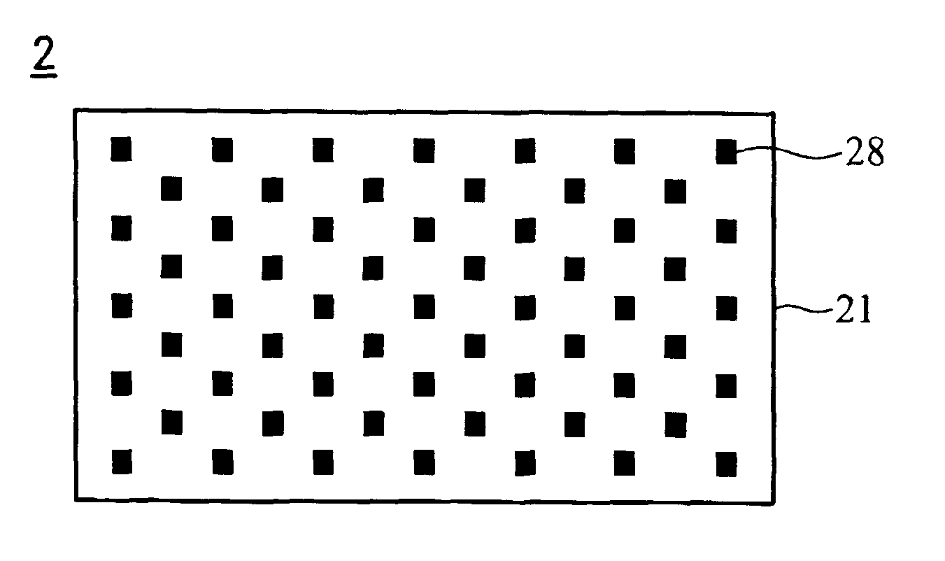
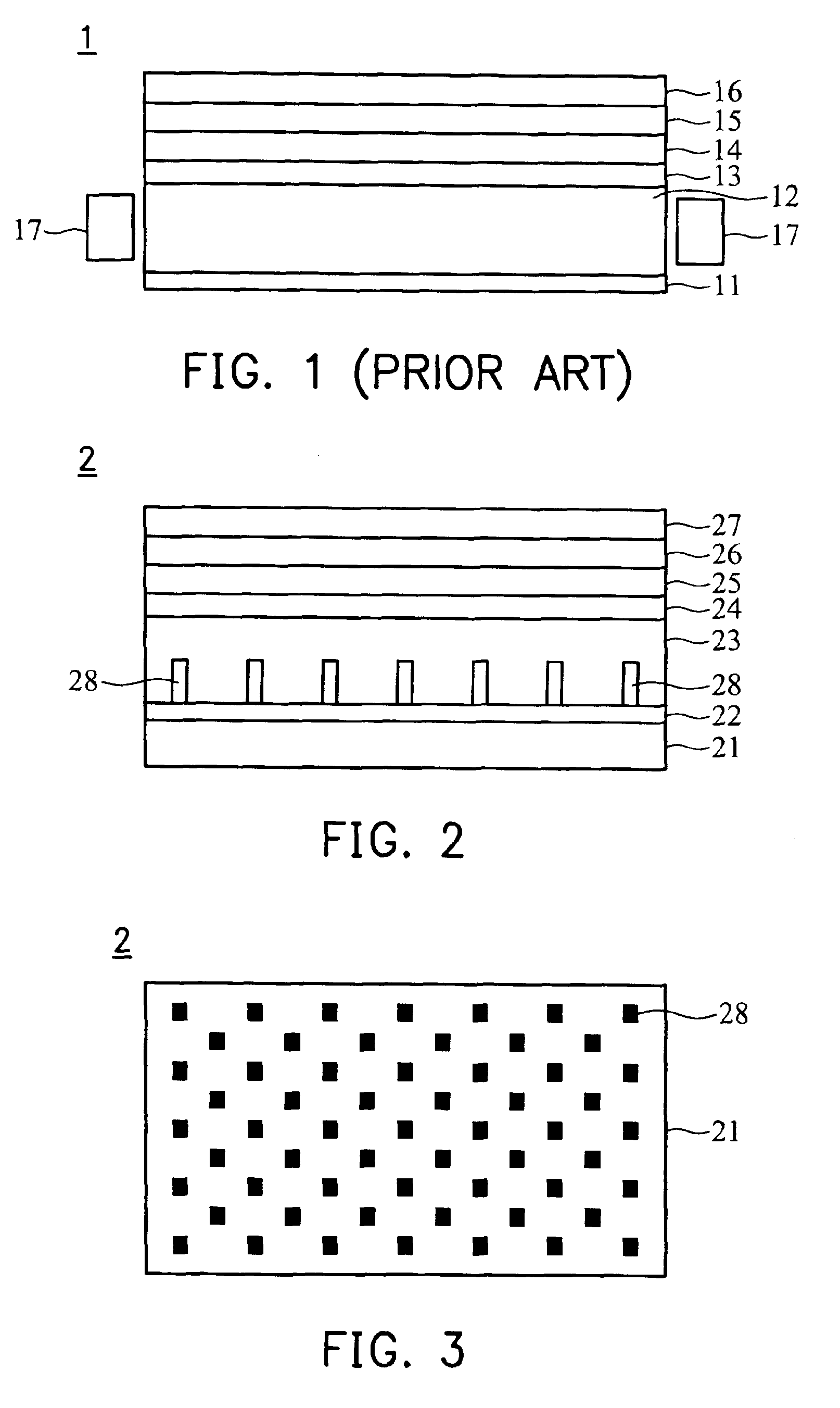
[0017]FIG. 2 is a sectional view of the backlight module in accordance with the present invention. As shown in FIG. 2, a printed circuit board 21 is disposed at the bottom of the LED backlight module 2. The printed circuit board 21 has a reflective material 22 coated on the top surface to reflect light such as the function of conventional reflector 11 mentioned in FIG. 1. Moreover, a plurality of LEDs 28, are electrically mounted on the printed circuit board 21 to provide illumination. The number of the LEDs 28 can be predetermined to meet the required illumination. Thus, the required illumination can be fulfilled by the printed circuit board 21 layout providing appropriate electric voltage and current to drive the LEDs 28. Particularly, the LEDs 28 are electrically mounted on the printed circuit board 21 by Surface Mount Technology (SMT).

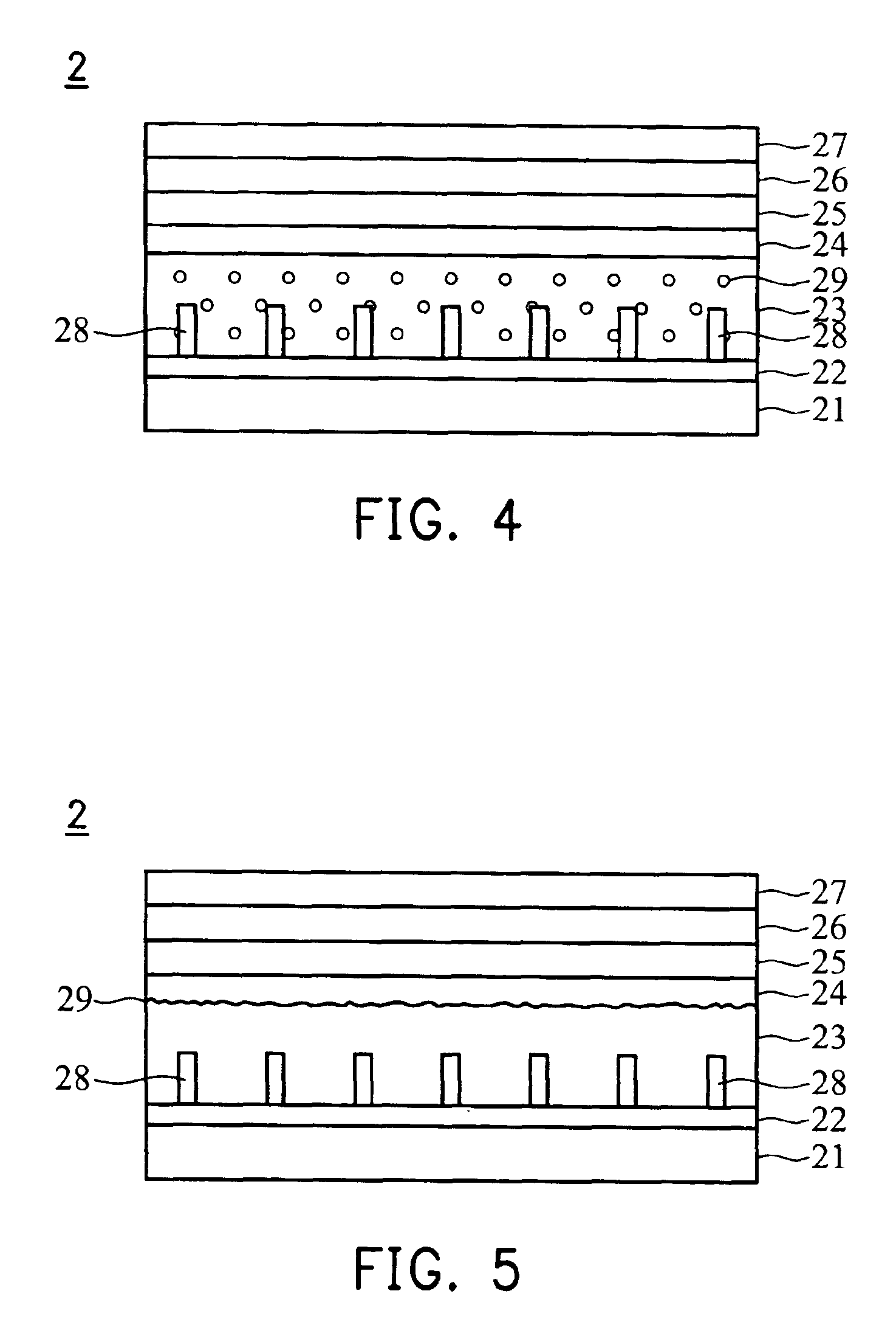
[0018]Furthermore, a light transmissive material 23 is coated on the printed circuit board 21, wherein the light transmissive material 23 can be P...


PUM


Abstract

An LED backlight module. The LED backlight module comprises a printed circuit board, a plurality of LEDs, and a light transmissive material. The LEDs are disposed on the printed circuit board. The light transmissive material is coated on the printed circuit board. Particularly, the LEDs are embedded in the light transmissive material and arranged in a matrix.

Description

BACKGROUND OF THE INVENTION[0001]1. Field of the Invention[0002]The present invention relates to a Light-Emitting Diode (LED) backlight module, and in particular to an LED backlight module that provides uniform illumination by embedding a plurality of LEDs in the light transmissive material and arranging them in a matrix.[0003]2. Description of the Related Art[0004]With the progress of semiconductor and flat panel display manufacturing technology, traditional Cathode Ray Tube (CRT) displays have increasingly been replaced by flat panel displays having small size and low radiation such as Liquid Crystal Displays (LCDs).[0005]In general, the conventional backlight module of an LCD uses the Cold Cathode Fluorescent Lamp (CCFL) as the light source. However, the Cold Cathode Fluorescent Lamp does not easily ignite in a low temperature environment, and an auxiliary heater is typically provided particularly in cold areas. Moreover, Cold Cathode Fluorescent Lamp requires adequate idle time ...

Claims


Application Information

Patent Timeline
IPC IPC(8): F21K99/00F21V7/04H05K1/02H05K3/28
CPCH05K1/0274F21K9/00H05K2201/2054H05K2201/0108H05K2201/10106H05K3/284
Inventor LEE, LIU-CHUNGLIN, CHIH-WEI
Owner AU OPTRONICS CORP
Why Eureka
Try Eureka