
Method for controlling and regulating a drive train

a technology of drive train and control train, which is applied in the direction of electric control, ignition automatic control, gearing, etc., can solve the problems of reducing input torque, affecting the operation of the drive train, so as to prevent the impact of the transmission input and output side, prevent the undesired vibration of the output train, and prevent the effect of shift operation

Inactive Publication Date: 2005-11-29
ZF FRIEDRICHSHAFEN AG
View PDF15 Cites 11 Cited by
  • Summary
  • Abstract
  • Description
  • Claims
  • Application Information

AI Technical Summary

Benefits of technology

[0008]With the inventive method for control and regulation of a drive train of a vehicle in which an old gear or a new gear can be disengaged or engaged via controllable free-wheel devices, it is advantageously possible to omit an unloading of the drive train, thus preventing a traction interruption during a higher traction shift.
[0009]This essential advantage results from the fact that the new gear or the operative connection between a controllable free-wheel device and a toothed wheel pair of the new gear is suddenly engaged, an actually introduced old gear or the operative connection between a controllable free-wheel device associated with the old gear and a toothed wheel pair that forms the ratio step of the old gear, being canceled almost simultaneously. As a result of this procedure, a power flow in the drive train advantageously is not interrupted during the gear shift proper and a traction interruption is prevented in a simple manner.
[0010]One other advantage of the inventive method is that undesired vibrations in the output train, occurring during the shift operation, are prevented. Such a second vibration occurs, for example, due to the sudden or spontaneous engagement of the new gear, since the rotary masses on the transmission input side are almost suddenly coupled by the free-wheel device of the new gear with the corresponding differential rotational speed, which results in a definite impact and high loading of the parts on the transmission input side and transmission output side.
[0011]To reduce said vibration, during the cycle of the method, it has been provided that an input torque of the drive unit be quickly reduced prior to engagement of the new gear whereby in the drive train a first vibration is advantageously generated which counters the second vibration that appears only after the first vibration. Due to the springs and rotary masses contained in the output unit, the reduction of the input torque leads at first only to a slight discharge of the output unit and after some time to a dampened vibration excitation of the output unit. Due to the engagement of the new gear and the second vibration produced thereby, the two counteracting vibrations diminish whereby the comfort in shifting is improved and the load of the parts of the drive train is reduced.
[0012]An excessive increase of the torque occurring in the drive train due to the engagement of the new gear is thus advantageously prevented by a previous reduction of the input torque of the drive unit and the drive train excited by the shifting or, an oscillating output torque is adjusted within the shortest time to a constant value of the new gear.

Problems solved by technology

Such a second vibration occurs, for example, due to the sudden or spontaneous engagement of the new gear, since the rotary masses on the transmission input side are almost suddenly coupled by the free-wheel device of the new gear with the corresponding differential rotational speed, which results in a definite impact and high loading of the parts on the transmission input side and transmission output side.
Due to the springs and rotary masses contained in the output unit, the reduction of the input torque leads at first only to a slight discharge of the output unit and after some time to a dampened vibration excitation of the output unit.

Method used


Image

  • Method for controlling and regulating a drive train
  • Method for controlling and regulating a drive train
  • Method for controlling and regulating a drive train

Examples


Embodiment Construction

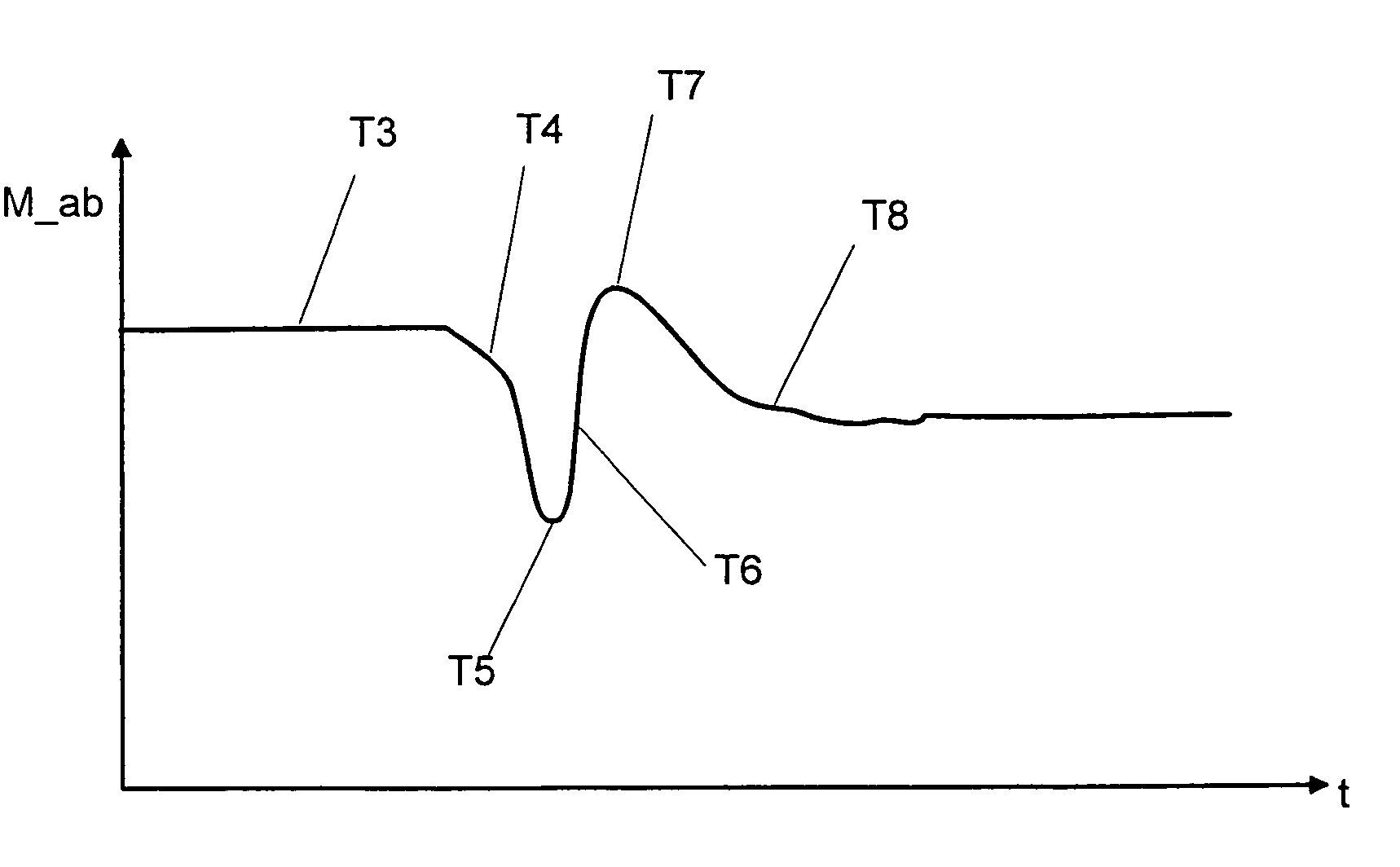
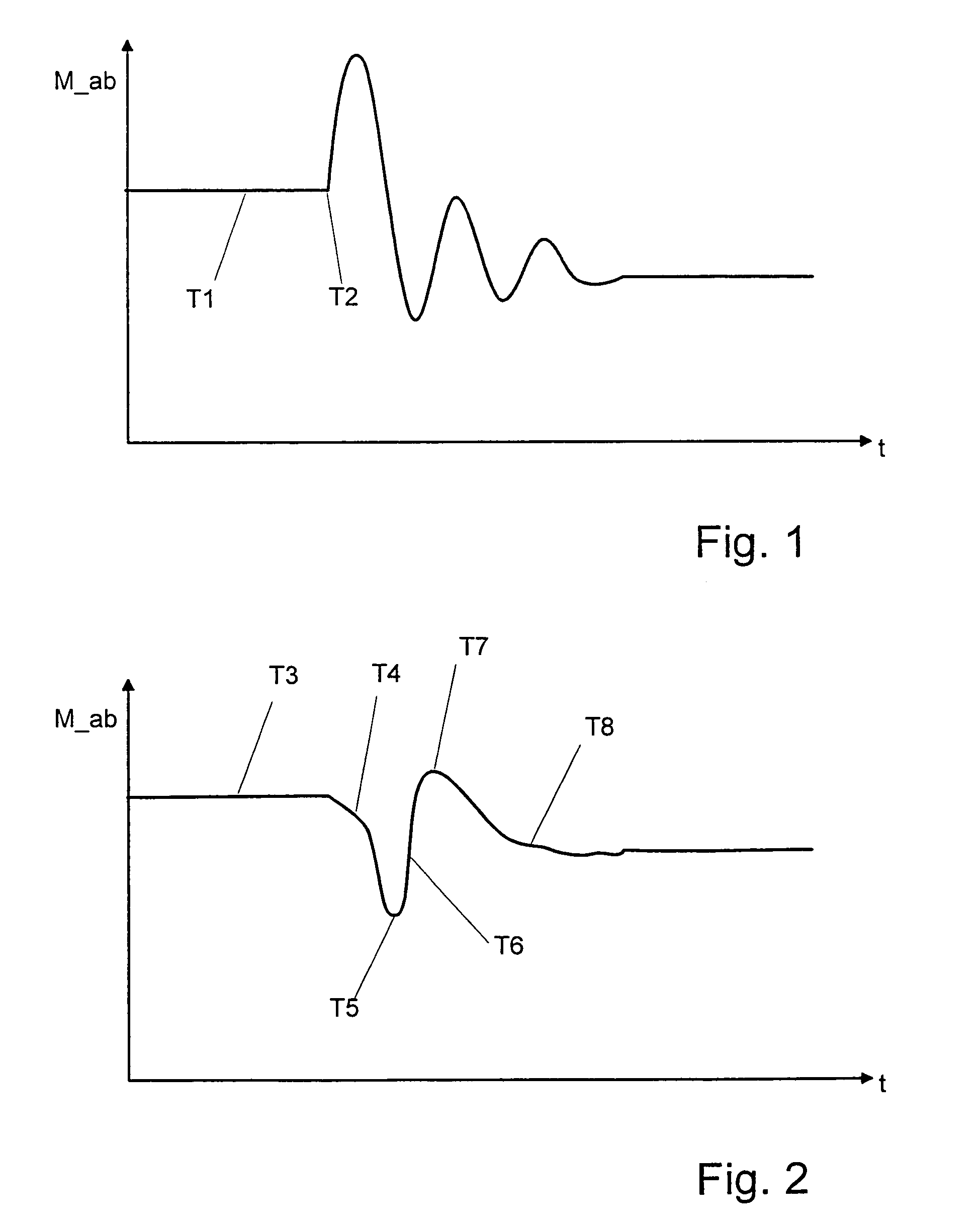
[0017]The mode of operation of the inventive method for control and regulation of a drive train of a vehicle is indicated with reference to the curves of an output torque M—ab during a shifting cycle of a higher traction shift shown in FIG. 1 and FIG. 2 where FIG. 2, unlike FIG. 1, reproduces the curve when the inventive method is used.

[0018]In FIG. 1 is shown the curve of a torque M—ab on an output unit of a drive train of a vehicle or of a motor vehicle during a shifting operation from an old gear to a new gear in the course of a higher traction shift such as it would shape itself when the invention method is used. The shown curve of the output torque M—ab is accomplished without a reduction of an input torque of a drive unit of the drive train. The output torque M—ab and the curve are plotted in FIG. 1 in the course of time t and have in a first range T1, in which in a transmission of the drive train an actual ratio of an old gear is adjusted, an at least approximate constant val...


PUM


Abstract

Described is a method for controlling and regulating a drive train of a vehicle comprising one drive unit, one transmission and one output unit. The transmission has controllable free-wheel device corresponding with toothed wheel pairs for disconnecting or connecting an old or a new gear and located on the input side one clutch. In the presence of a shifting signal for carrying out a higher traction shift, an input torque of the drive unit is quickly reduced so that a first vibration is induced in the drive unit. During a subsequent shifting, an operative connection is abruptly created between a free-wheel device and a toothed wheel pair corresponding therewith in a manner such that a second vibration counteracting the first vibration is produced in the drive train. With the engagement of the new gear the operative connection of the old gear is canceled as a result of a torque reversal from a pull torque to a push torque.

Description

FIELD OF THE INVENTION[0001]The invention relates to a method for controlling and regulating a drive train of a vehicle having one drive unit, one transmission and one output unit.BACKGROUND OF THE INVENTION[0002]In DE 197 35 759 A1 a method is described for control of an automatic drive device which has one propeller source, one speed-change transmission with several toothed wheel sets that can be coupled, one fluid-actuatable main clutch and a fluid-actuatable switch means for actuating the individual toothed wheel sets. In addition, an electronic control is provided for the control of the main clutch and of the switch means, the main clutch being retained in a slipping state for attaining a changeover of the switch means free of traction interruptions.[0003]To switch the forward gears, there is provided as coupling element or switch means respectively on a transmission input shaft and on a transmission output shaft, one draw key device actuated by a hydraulic adjusting element fo...

Claims


Application Information

Patent Timeline
Patent Type & Authority Patents(United States)
IPC IPC(8): B60W10/02B60W10/00B60W10/04B60W10/06B60W10/10B60W30/18F02D29/00F02D41/04F02P5/15F16D41/06F16H3/091F16H3/10F16H61/04F16H61/684F16H63/50
CPCB60W10/06B60W10/11B60W30/19F16H3/10F16H61/0437F16H63/502B60K2741/105Y10T477/6403B60W2710/025B60W2710/0666F16H3/0915F16H61/684F16H63/46F16H2306/44F16H2306/46Y10T74/1926Y10T477/638Y10T477/6407B60K2741/225B60W10/02B60W10/10B60W30/1819
Inventor DREIBHOLZ, RALFBAASCH, DETLEFGUMPOLTSBERGER, GERHARD
Owner ZF FRIEDRICHSHAFEN AG
Learn More