Apparatus for use in arthroplasty of the knees

a knee joint and arthroplasty technology, applied in the field of arthroplasty apparatus for knee joint arthroplasty, can solve the problems of increasing the risk of surgery related complications, increasing the operation time, and increasing the discomfort of the patient, so as to achieve the effect of reducing the operating tim

Inactive Publication Date: 2005-11-29
SMITH & NEPHEW INC
View PDF30 Cites 271 Cited by
  • Summary
  • Abstract
  • Description
  • Claims
  • Application Information

AI Technical Summary

Benefits of technology

[0048]Preferably, the guide jig incorporates a template for guiding the movement of the body of the cutting device relative to the tibia. The template of the jig may be a recess defined in the jig. Typically, the cutting device will be provided with a guide pin that projects into the recess of the jig for facilitating the guiding of the cutting device. In another embodiment, the guide jig may comprise a pentagraph arrangement on which the cutting device is arranged.
[0054]Preferably, the tibial implant will be adapted for being mated with the cutter device for inhibiting lifting of the cutter device from the tibial implant during the movement of the tibia about the femur.
[0062]The further blade of the cutter will usually be dimensioned such that the resulting channel resected into the femur will be capable of accommodating a fin of a femoral prosthesis. By resecting the channel into the femur at the same time as resecting the layer of bone therefrom, operating time may be reduced and the channel may be formed with greater accuracy.

Problems solved by technology

This leads to an increase in operation time with an associated increase in the risk of surgery related complications.
Such additional surgical intervention following fitting of the trial implants potentially leads to subsequent increased discomfort for the patient and increased healing times.

Method used


Image

  • Apparatus for use in arthroplasty of the knees
  • Apparatus for use in arthroplasty of the knees
  • Apparatus for use in arthroplasty of the knees

Examples


Embodiment Construction

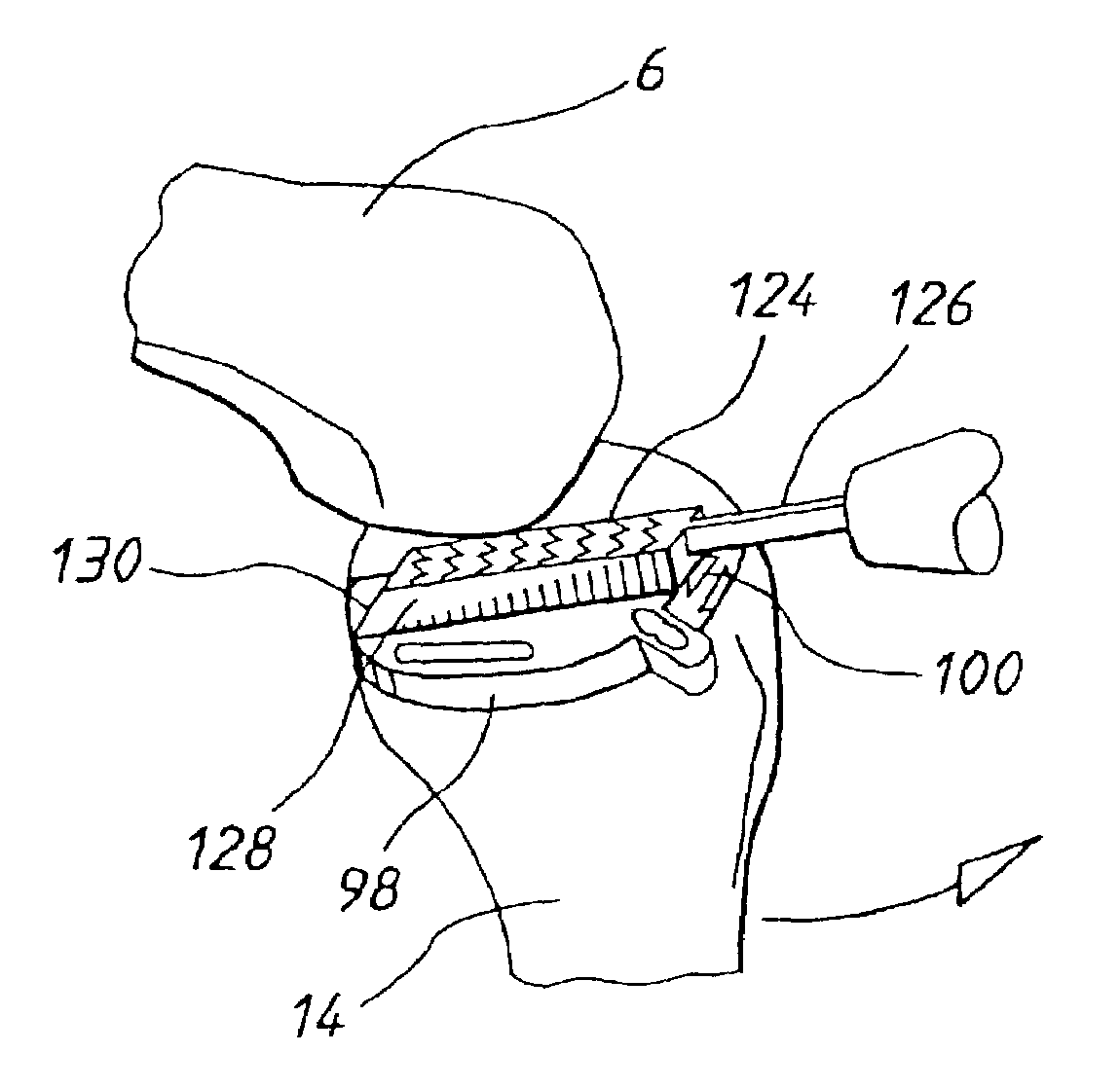
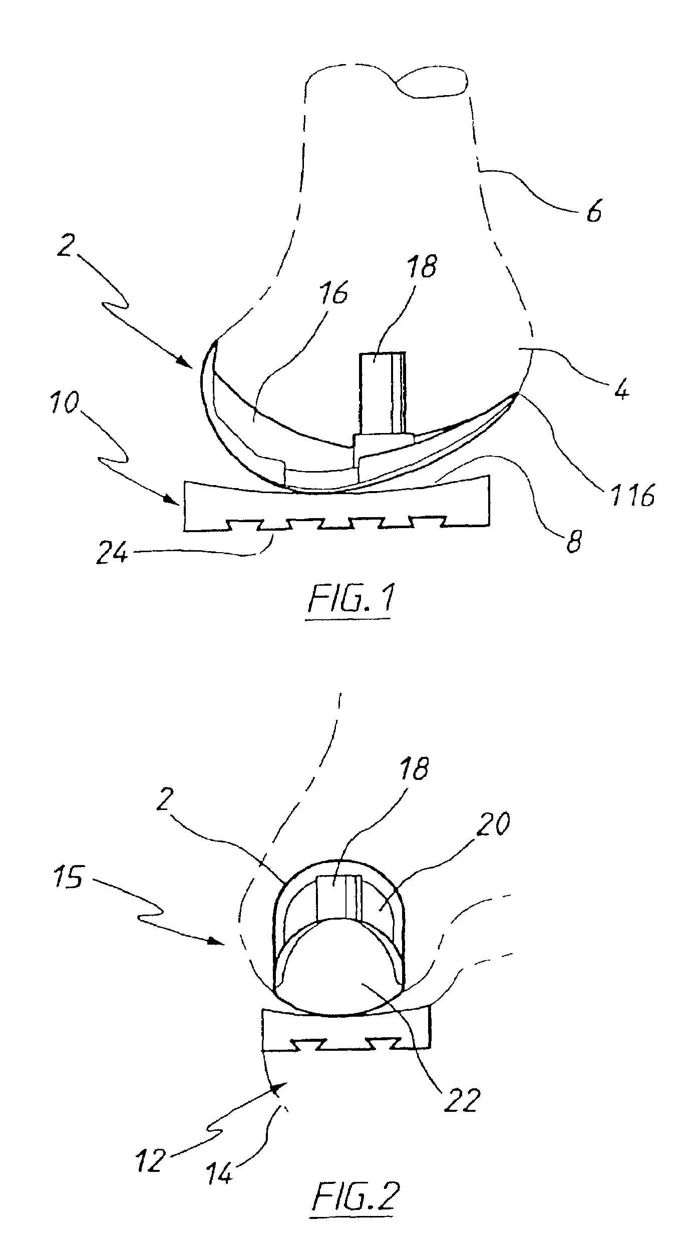
[0105]The femoral prosthesis 2 shown in FIG. 1 is fitted to the medial condyle 4 of the femur 6 and abuts articulating surface 8 of the tibial prosthesis 10 fitted on the corresponding medial condyle 12 of the tibia 14, for articulation thereon as the tibia undergoes flexion and extension about the knee joint 15. The positioning of the femoral prosthesis 2 and the tibial prosthesis 10 is more clearly shown in FIG. 2.

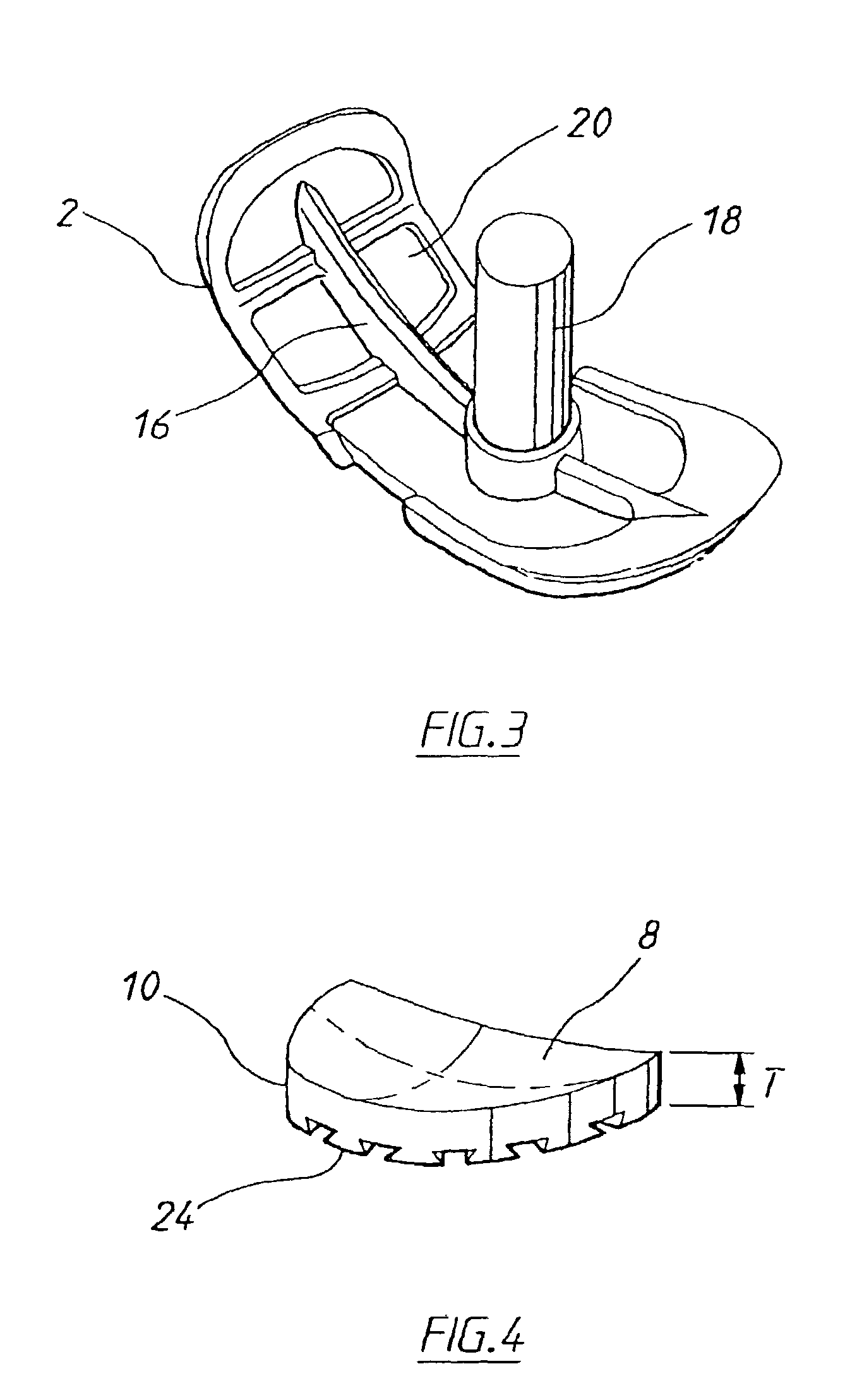
[0106]As shown in FIG. 3, the femoral prosthesis 2 is provided with a centrally orientated upstanding fin 16 incorporating a peg 18 projecting from an interior face 20 of the prosthesis.

[0107]The opposite outer face 22 has a curved contour for facilitating movement of the tibia about the femur. The interior face 20 of the femoral prosthesis is textured to enhance binding of bonding cement used to fix the prosthesis to the femur. The prosthesis itself is formed from a cast cobalt chromium molybdenum alloy conventionally used in the manufacture of such prostheses.

[0108]The...


PUM


Abstract

A cutting device for being inserted into a knee joint between the tibia and the femur, wherein the cutting device is adapted for resecting bone from the femur to a desired depth in a path of travel of the tibia when located in the knee joint and operated as the tibia is moved through an arc of motion about the femur between backward and forward positions. A cutting device is also disclosed for being inserted into a knee joint between the tibia and the femur for resecting bone from the tibia to a desired depth to form a recess in a condyle of the tibia for reception of a tibial implant, comprising a body being located between the tibia and the femur, a cutter for resecting the bone from the tibia to form the recess and a drive mechanism for driving the cutter to resect the bone and being arranged in the body, wherein the cutter is mounted on the body and protrudes therefrom for resecting the bone from the tibia.

Description

CROSS-REFERENCE TO RELATED APPLICATIONS[0001]This application is a continuation of International Application No. PCT / AU01 / 00262 filed on Mar. 9, 2001 and published in English as International Publication Number WO 01 / 66022 A1 on Sep. 13, 2001, which claims priority to Australian Patent Application No. PQ 6161 filed on Mar. 10, 2000, Australian Patent Application No. PQ 8999 filed on Jul. 25, 2000, Australian Patent Application No. PQ 9044 filed on Jul. 27, 2000, and Australian Patent Application No. PQ 9045 filed on Jul. 27, 2000.FIELD OF THE INVENTION[0002]The present invention relates to apparatus for use in arthroplasty on a knee joint and methods utilising the apparatus.BACKGROUND OF THE INVENTION[0003]Various methods and apparatus for performing knee arthroplasty and unicondylar knee arthroplasty in particular, are known in the art. The known methods involve resection of the tibia and femur for fitting of trial tibial and femoral implants, respectively. Once the bone has been r...

Claims


Application Information

Patent Timeline
Patent Type & Authority Patents(United States)
IPC IPC(8): A61B17/56A61B17/14A61B17/15A61B17/16A61B17/17A61F2/38
CPCA61B17/154A61B17/1659A61B17/1675A61B17/1764A61B17/155A61B17/157A61B2017/1602A61F2002/3895
Inventor PINCZEWSKI, LEO ARIEHPARKER, STEPHEN JOHNMARIK, GREGROCCO, RICHARD A.
Owner SMITH & NEPHEW INC
Why Eureka
Try Eureka