
Disk drive comprising a pulse width modulated demand limit circuit for enhancing power management during spin-down

a demand limit circuit and spin-down power management technology, applied in the field of disk drives, can solve the problems of vcm driver excessive current in order to decelerate the head, the analog and digital circuitry which control the power down sequence may malfunction or shut down, and the power down operation may be questionabl

Active Publication Date: 2005-11-29
WESTERN DIGITAL TECH INC
View PDF7 Cites 129 Cited by
  • Summary
  • Abstract
  • Description
  • Claims
  • Application Information

AI Technical Summary

Benefits of technology

[0020]In yet another embodiment, the disk drive further comprises a voltage regulator responsive to the internal supply voltage for generating a regulated voltage, wherein the regulated voltage is applied to the control input of the VCM while the demand limit control signal is deactivated.
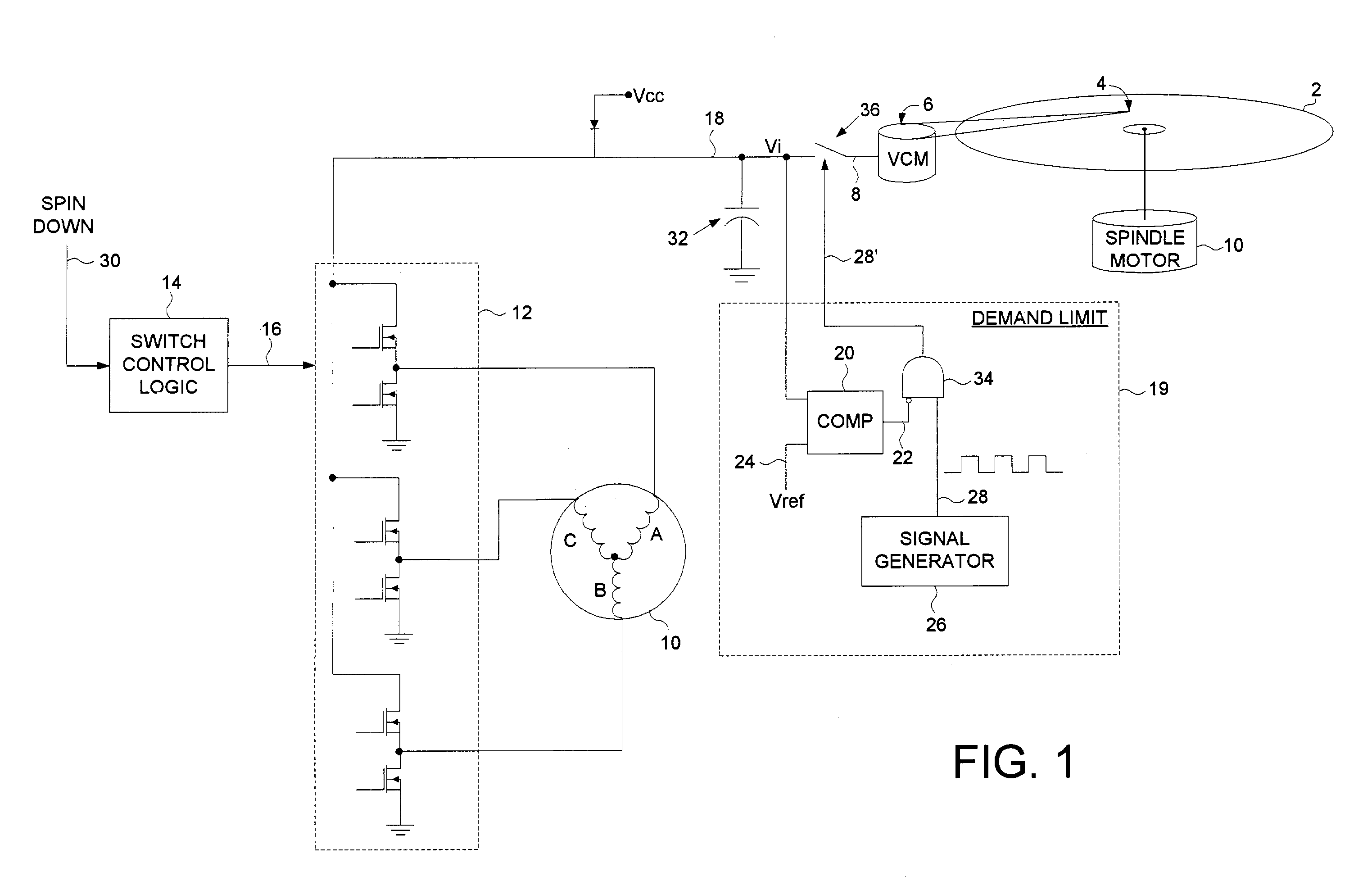
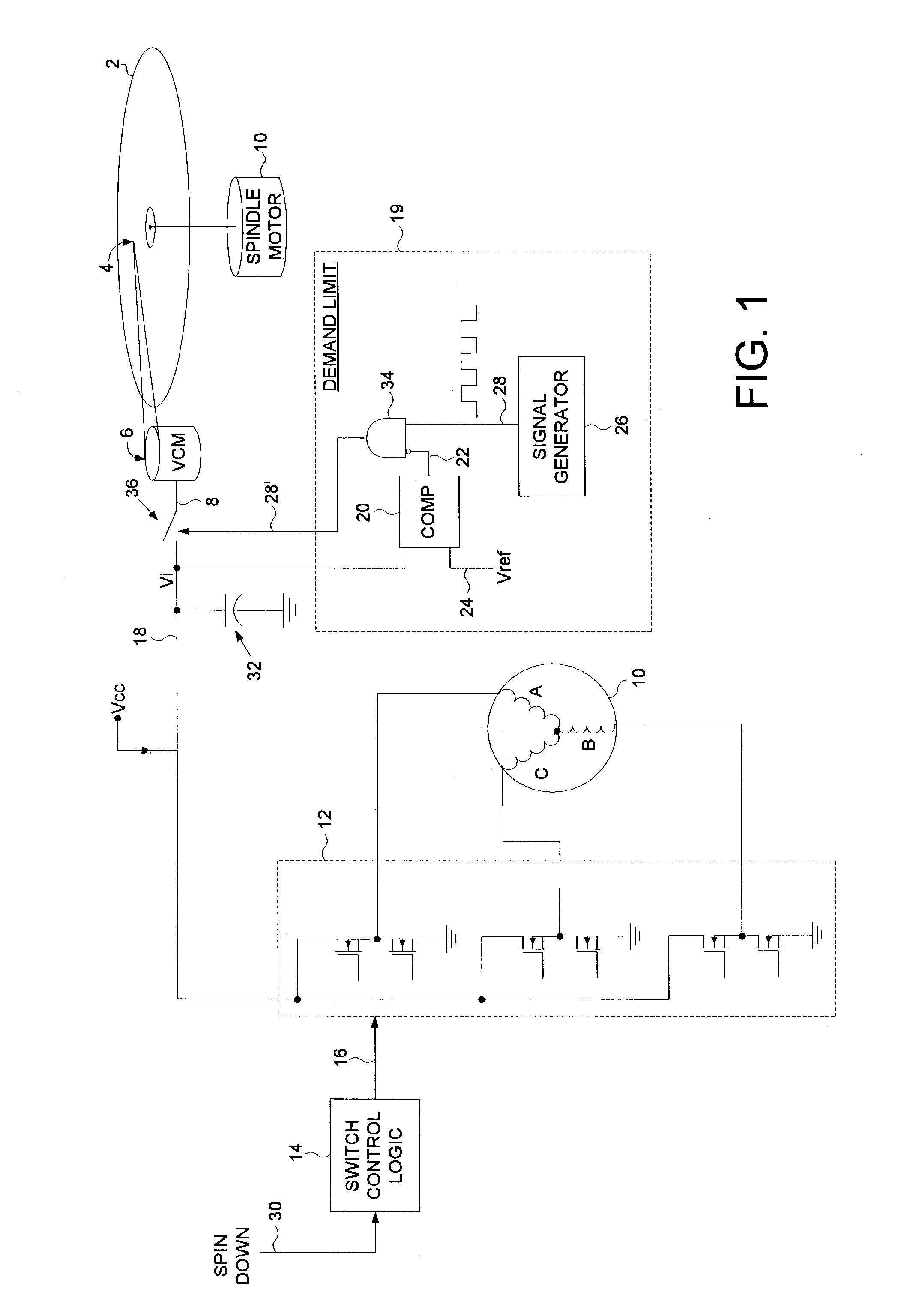
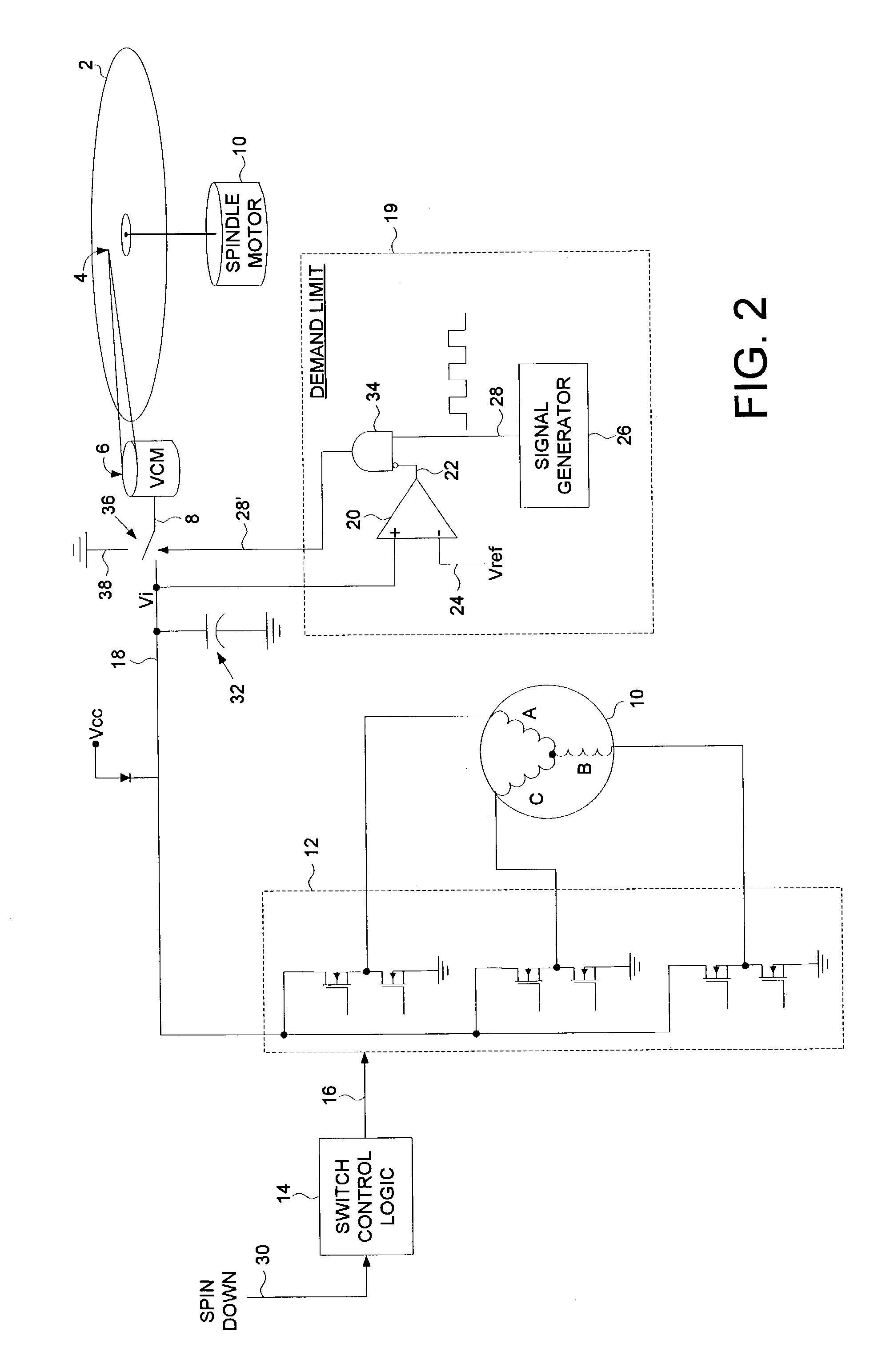
[0021]The present invention may also be regarded as a method of operating a disk drive. The disk drive comprises a disk, a head, a voice coil motor (VCM) for actuating the head radially over the disk, the VCM having a control input, and a spindle motor for rotating the disk. The spindle motor comprises a plurality of windings and a rotor rotatable at a variable spin rate wherein the rotor generates a back EMF (BEMF) voltage across the windings proportional to the spin rate of the rotor. A plurality of switching elements are coupled to the windings, and switch control logic generates switch control signals applied to the switching elements for commutating the spindle motor during normal operation and for generating an internal supply voltage from the BEMF voltage during a spin-down mode, the internal supply voltage applied to the control input of the VCM for parking the head. The internal supply voltage is compared to a threshold in order to activate and deactivate a demand limit control signal. A periodic signal is generated for periodically disconnecting the internal supply voltage from the control input of the VCM while the demand limit control signal is active.

Problems solved by technology

This limited internal supply must provide enough current to allow all shutdown activities to take place, including the sequencer and controls necessary to make the shutdown events happen properly.
If the internal supply voltage drops below a certain threshold for an extended period of time during a power failure mode, the analog and digital circuitry which control the power down sequence may malfunction or shut down.
This can typically occur if the VCM driver draws an excessive amount of current from the internal supply voltage.
For example, if the head is in the middle of a seek operation when power failure occurs, the VCM driver may draw excessive current in order to decelerate the head.
Either of these events may pull down the internal supply voltage beyond a safe level, thereby rendering the power down operation questionable.
However, this increases the overall cost of the disk drive since the design restrictions on the spindle motor both raise its costs and put stringent requirements on the design of the rest of the disk drive.
Yet another problem identified with prior art disk drives during a normal spin-down operation is that the head is typically positioned over the landing zone on the disk while the disk is still rotating at a high RPM resulting in undesirable head wear.
The landing zone is typically textured to reduce the stiction force during spin-up; however, this extremely hard textured surface also wears on the head during spin-down.
Because prior art techniques position the head over the landing zone while the disk is still spinning at a high RPM, head wear increases due to the increased time to brake the spindle motor.
This creates a low voltage tolerance problem since the back EMF from the spindle motor is proportional to design RPM, not to actual operating RPM.
Delaying head parking during spin-down using these reduced voltage spindle motors to minimize head wear causes additional sag in the internal supply voltage due to even lower RPM.

Method used


Image

  • Disk drive comprising a pulse width modulated demand limit circuit for enhancing power management during spin-down
  • Disk drive comprising a pulse width modulated demand limit circuit for enhancing power management during spin-down
  • Disk drive comprising a pulse width modulated demand limit circuit for enhancing power management during spin-down

Examples


Embodiment Construction

[0034]FIG. 1 shows a disk drive according to an embodiment of the present invention comprising a disk 2, a head 4, a voice coil motor (VCM) 6 for actuating the head 4 radially over the disk 2, the VCM 6 having a control input 8, and a spindle motor 10 for rotating the disk 2. The spindle motor 10 comprises a plurality of windings and a rotor rotatable at a variable spin rate wherein the rotor generates a back EMF (BEMF) voltage across the windings proportional to the spin rate of the rotor. A plurality of switching elements 12 are coupled to the windings and switch control logic 14 generates switch control signals 16 applied to the switching elements 12 for commutating the spindle motor 10 during normal operation and for generating an internal supply voltage (Vi) 18 from the BEMF voltage during a spin-down mode, the internal supply voltage 18 applied to the control input 8 of the VCM 6 for parking the head 4. A demand limit circuit 19 controls the amount of current drawn by the VCM ...


PUM

PropertyMeasurementUnit
currentaaaaaaaaaa
currentaaaaaaaaaa
voltageaaaaaaaaaa

Abstract

A disk drive is disclosed comprising a head, a disk and a spindle motor for rotating the disk. An internal supply voltage is generated from a back EMF (BEMF) voltage across the windings of the spindle motor. The internal supply voltage is applied to a voice coil motor for use in parking the head during a spin-down mode. The internal supply voltage is compared to a threshold in order to activate a demand limit control signal. A periodic signal periodically disconnects the internal supply voltage from the VCM while the demand limit control signal is active.

Description

CROSS REFERENCE TO RELATED APPLICATIONS AND PATENTS[0001]This application is related to U.S. Pat. No. 5,898,283 entitled “VOLTAGE FEED FORWARD CONTROL SYSTEM FOR A SPINDLE MOTOR OF A DISK DRIVE” issued on Apr. 27, 1999, the disclosure of which is incorporated herein by reference.BACKGROUND OF THE INVENTION[0002]1. Field of the Invention[0003]The present invention relates to disk drives for computer systems. More particularly, the present invention relates to a disk drive comprising a pulse width modulated demand limit circuit for enhancing power management during spin-down.[0004]2. Description of the Prior Art[0005]When the disk spins down in a disk drive it is important to park the head before the air bearing dissipates to prevent damage to the head and / or the disk. In disk drives wherein the head is parked in a landing zone on the disk, it is also important to brake the spindle motor as quickly as possible to minimize head wear. Conventionally, when power is removed from the disk ...

Claims


Application Information

Patent Timeline
Patent Type & Authority Patents(United States)
IPC IPC(8): G11B5/54G11B21/02
CPCG11B5/54
Inventor BENNETT, GEORGE J.RYAN, ROBERT P.
Owner WESTERN DIGITAL TECH INC
Learn More