Memory device

Inactive Publication Date: 2005-11-29
LONGITUDE LICENSING LTD
View PDF16 Cites 36 Cited by
  • Summary
  • Abstract
  • Description
  • Claims
  • Application Information

AI Technical Summary

Benefits of technology

[0012]It is, therefore, one objective of the present invention to provide a memory device which is capable of decreasing reflectio

Problems solved by technology

However, according to a study performed by the present inventors, it was found that there are various factors that would prevent the operation at high speed of these types of memory device, and it was further found that neither i

Method used


Image

  • Memory device
  • Memory device
  • Memory device

Examples


Embodiment Construction

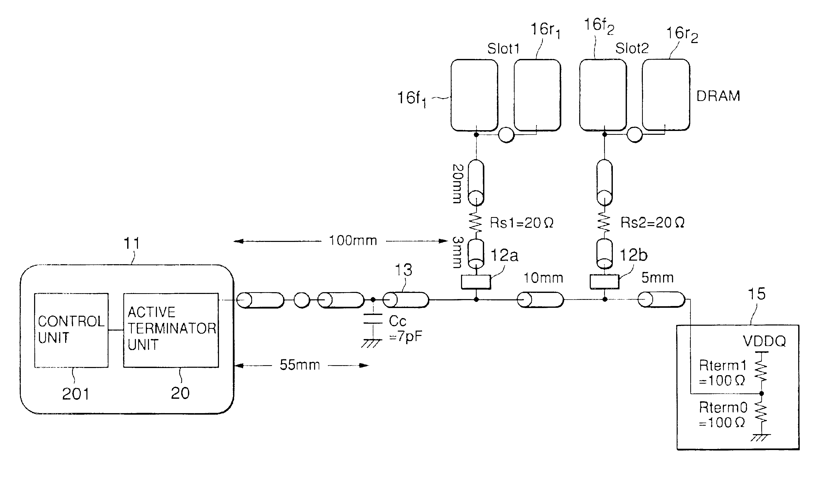
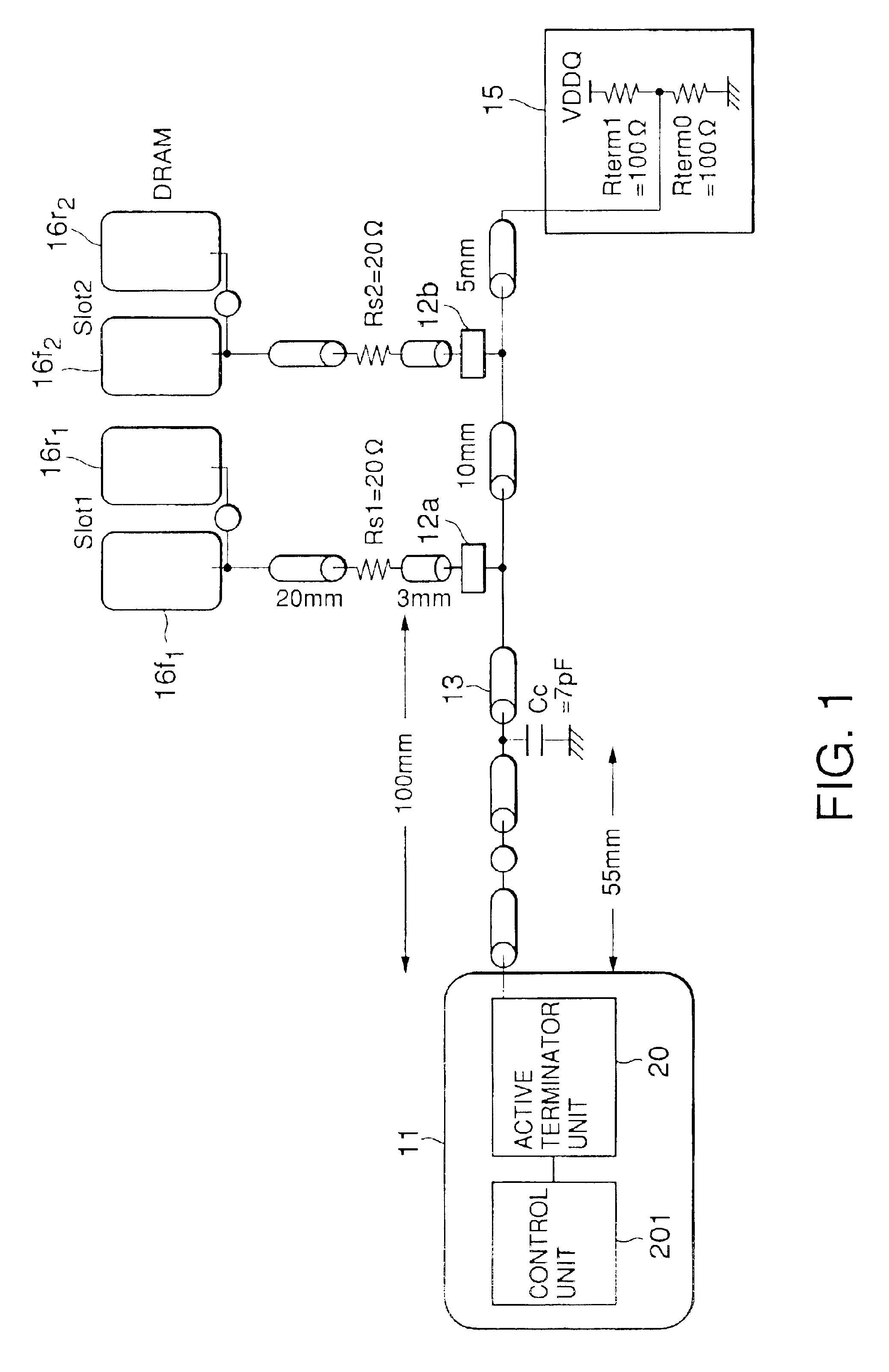
[0066]Referring to FIG. 1, description will be made about a memory device according to a first embodiment of the present invention. The memory device in FIG. 1 is operated in accordance with SSTL, and a controller 11 and multiple connectors (in this embodiment, connectors 12a and 12b) are mounted on a motherboard (not shown). A slot wherein connection terminals are arranged is provided for the connectors 12a and 12b, and in FIG. 1, the connection terminals of the connectors 12a and 12b and the controller 11 are connected by a data bus 13 that is wired or printed on the motherboard. While multiple buses are actually arranged on the motherboard, for simplification of the explanation, only one data bus 13, horizontally extended in FIG. 1, is shown in this example. One end of the data bus 13 is connected to the controller 11, and the other end is connected to a terminating set 15 that will be described later. While a command address bus has the same topology as the data bus, for simplif...


PUM


Abstract

In a memory device having a controller and multiple memory modules both of which are mounted together on a motherboard, a high-speed operation is executed by suppressing waveform distortion caused by signal reflection. Since signal reflection occurs when a controller performs the writing/reading of data relative to memory units on memory modules, active terminator units are included in the controller and the memory units. These active terminator units are provided for a data bus and/or a clock bus in order to terminate these buses in memory units. The active terminator units provided for the controller and the memory units may be put into an inactive state when data is to be received.

Description

BACKGROUND OF THE INVENTION[0001]The present invention relates to a memory device, and relates in particular to a memory device having a circuit configuration that ensures an increase in the operating speed.[0002]While memory devices have been highly integrated, interfaces have been developed that permit the memory devices to be operated at high speeds and with a low signal amplitude. To this end, SSTL (Stub Series Termination Logic) has been proposed as the standards for these interfaces. In order to increase the operating speeds of DRAM, which is one type of memory devices, a DDR (Double Data Rate) method has been also proposed. In the DDR method, the data rate can be doubled by inputting and outputting data in synchronism with the leading edge and the trailing edge of each clock.[0003]These types of memory devices have a configuration wherein multiple memory modules are mounted on a motherboard in parallel and at predetermined distances or intervals. According to this configurati...

Claims


Application Information

Patent Timeline
IPC IPC(8): G06F3/00G06F12/00G06F13/16G11C5/06G11C7/00G11C7/10G11C11/401G11C11/4093H03K19/0175
CPCG11C5/063G11C7/10G11C7/1048G11C11/4093G11C7/00
Inventor FUNABA, SEIJINISHIO, YOJI
Owner LONGITUDE LICENSING LTD
Why Eureka
Try Eureka