Packet transfer method and apparatus, and packet communication system

a packet communication system and packet transfer technology, applied in data switching networks, multiplex communication, digital transmission, etc., can solve the problems of inability to ensure the calculation time necessary for switch connection setting, and difficulty in increasing switching capacity, so as to increase the number of packets transferable on the network, ensure the calculation time necessary, and increase the size of the switching unit

Inactive Publication Date: 2005-11-29
NEC CORP
View PDF24 Cites 36 Cited by
  • Summary
  • Abstract
  • Description
  • Claims
  • Application Information

AI Technical Summary

Benefits of technology

[0032]It is an object of the present invention to provide a packet transfer method and apparatus and a packet communication system, which can increase the size of switching unit or transfer time unit of a crossbar switch section constructing a packet transfer apparatus, ensure the calculation time necessary for switch connection setting even when the number of input / output interfaces or input / output interface speed increases, and increase the number of packets transferable on a network.
[0033]It is another object of the present invention to provide a packet transfer method and apparatus and a packet communication system, which can sufficiently increase the minimum value of a packet to be transferred on a network, and increase the number of packets transferable on the network without any degradation in throughput of switch operation due to a free band.
[0034]It is still another object of the present invention to provide a packet transfer method and apparatus and a packet communication system, which can increase the number of packets transferable on the network without wasting a free band even when a packet is segmented into device cell units and switched.

Problems solved by technology

After the interface speed is increased, calculation for switch connection setting can be executed for only a smaller number of interfaces within the defined transfer time unit τ. That is, in this case as well, it is difficult to increase the switching capacity.
Especially, in a large-scale router apparatus, when a device cell of 64 bytes (minimum length of an IP packet) or less is defined, the calculation time necessary for switch connection setting cannot be ensured.
The above-described Japanese Patent Laid-Open No. 63-197148 also suffers the same problem as described above because it is suggested that a routing processing means in a packet switching network actually segments a long packet into device cells and switches them.

Method used


Image

  • Packet transfer method and apparatus, and packet communication system
  • Packet transfer method and apparatus, and packet communication system
  • Packet transfer method and apparatus, and packet communication system

Examples


Embodiment Construction

[0056]An embodiment of the present invention will be described below with reference to the accompanying drawings. The present invention can be applied to general packets or frames to be transferred on a network. In this embodiment, a description will be made by exemplifying a router apparatus for processing an IP packet of these packets or frames.

(1) Arrangement of Network

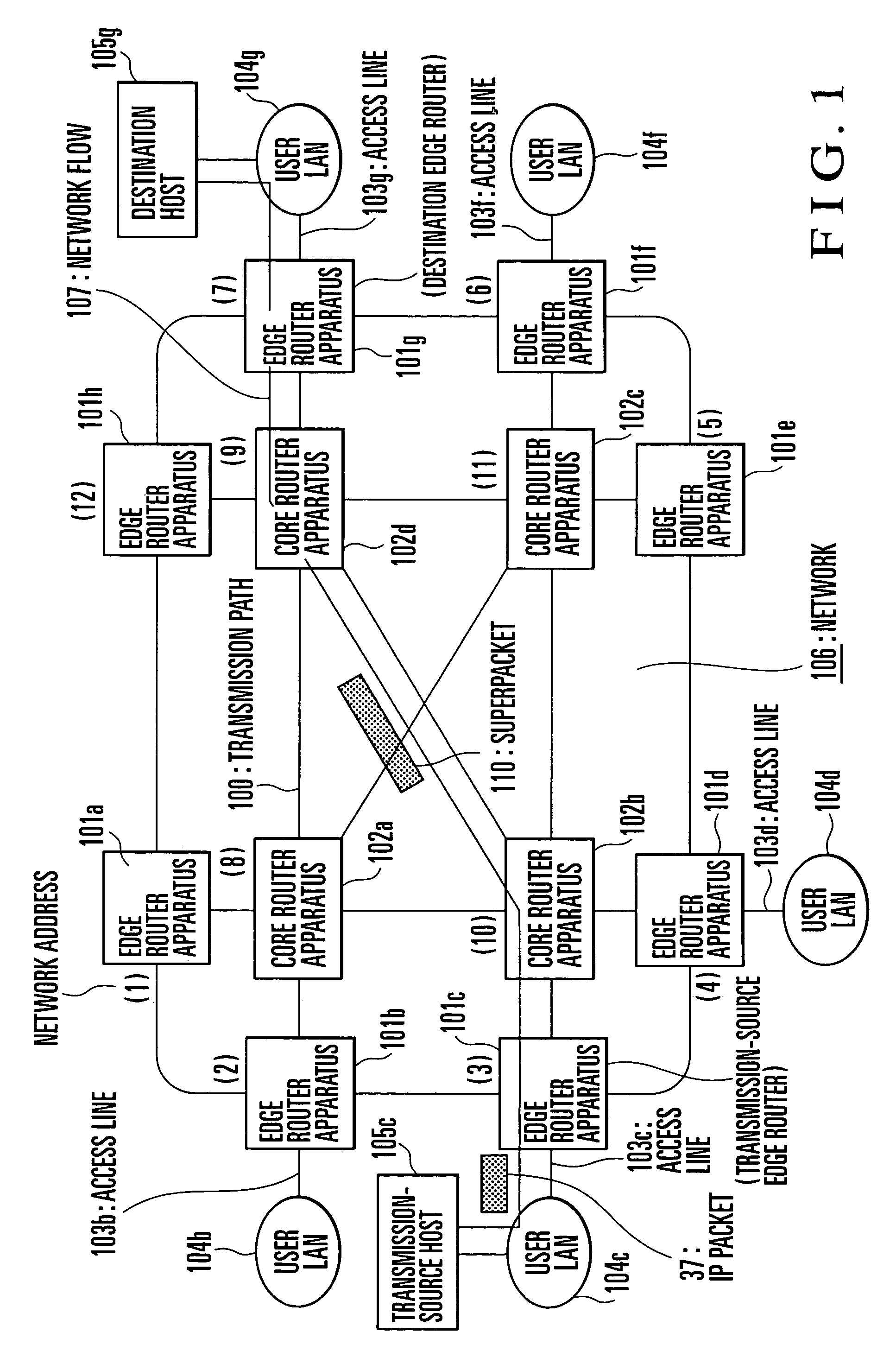
[0057]FIG. 1 shows the arrangement of a packet communication system to which this embodiment is applied. As shown in FIG. 1, as a characteristic feature, a network for implementing this embodiment has two types of router apparatuses: core router apparatuses and edge router apparatuses. In the network of this embodiment, not only these router apparatuses but also user LANs as in the conventional network described with reference to FIG. 15 are arranged. The core router apparatuses and edge router apparatuses are connected through transmission paths 100. Each edge router apparatus and a corresponding user LAN are conn...


PUM


Abstract

In a packet transfer method, a packet to be transferred to a destination access network is generated and transmitted to a transmission-source packet transfer apparatus connected to the transmission-source access network. The packet is converted into a superpacket having a length n times (n is an integer of 2 or more) larger than a fixed-length cell as a switching unit of a relay apparatus arranged on a network serving as a backbone, and sent to the network. The superpacket is relayed using the relay apparatus and transferred to a destination packet transfer apparatus connected to the destination access network. The packet generated by the transmission-source access network is reassembled on the basis of the superpacket transferred from the network, and sent to the destination access network. A packet transfer apparatus and packet communication system are also disclosed.

Description

BACKGROUND OF THE INVENTION[0001]The present invention relates to a packet transfer method and apparatus and a packet communication system.(1) Arrangement of Conventional Network[0002]FIG. 15 shows the arrangement of a network conventionally used for packet communication. A description will be made below by exemplifying, as a packet transfer apparatus, a router apparatus for transferring an IP (Internet Protocol) packet. As shown in FIG. 15, a plurality of router apparatuses for relaying a packet are arranged in the network. Four router apparatuses 1a to 1d are exemplified in FIG. 15. These router apparatuses are connected through transmission paths. For example, the router apparatus 1a and router apparatus 1b are connected through a transmission path 2ab. The remaining router apparatuses are connected through transmission paths 2ac, 2ad, 2bc, 2bd, and 2cd. Each router apparatus is connected to one or a plurality of user LANs (Local Area Networks) as an example of an access network....

Claims


Application Information

Patent Timeline
Patent Type & Authority Patents(United States)
IPC IPC(8): H04J3/24H04L47/43H04L12/28H04L12/46H04L12/66
CPCH04L12/4633H04L12/5601H04L49/3081H04L69/16H04L69/168H04L2012/5662H04L2012/5667
Inventor NISHIHARA, MOTOO
Owner NEC CORP
Why Eureka
Try Eureka